Intra-Oral Distraction Device

a distraction device and intraoral technology, applied in the field of intraoral distraction devices, can solve the problems that the treatment option of many patients is not enough, and the vertical regeneration alone cannot provide the necessary treatment option, and achieve the effect of angular bone regeneration

Inactive Publication Date: 2008-12-18
STEVENS INSTITUTE OF TECHNOLOGY
View PDF12 Cites 9 Cited by
  • Summary
  • Abstract
  • Description
  • Claims
  • Application Information

AI Technical Summary

Benefits of technology

[0014]The main body of the connecting wedge is fitted within the connecting wedge housing of the threaded rod. With the main body securely attached to the threaded rod, the connecting wedge extensions are engaged within the lower transport plates, and the threaded rod is stabilized by the lower transport plates. Further, when the threaded rod, the connecting wedge, and the lower transport plates are assembled, the threaded rod extends at an angle that is offset relative to the lower transport plates. That is, the threaded rod and the lower transport plates form an angular relationship that is not necessarily parallel or perpendicular. The angular arrangement of the threaded rod relative to the lower transport plates allows for angular distraction and angular bone regeneration.
[0015]In another embodiment of the present invention, the distraction device includes a threaded rod engaged within a correspondingly threaded hub. The distraction device also includes a shaft that passes horizontally through the hub, wherein each end of the shaft extending out of the sides of the hub are secured by a lower transport plate. The threaded rod,...

Problems solved by technology

However, conventional distraction devices for intra-oral distraction facilitate bone regeneration in only a vertical direction.
Because bone geometries vary f...

Method used


Image

  • Intra-Oral Distraction Device
  • Intra-Oral Distraction Device
  • Intra-Oral Distraction Device

Examples


Embodiment Construction

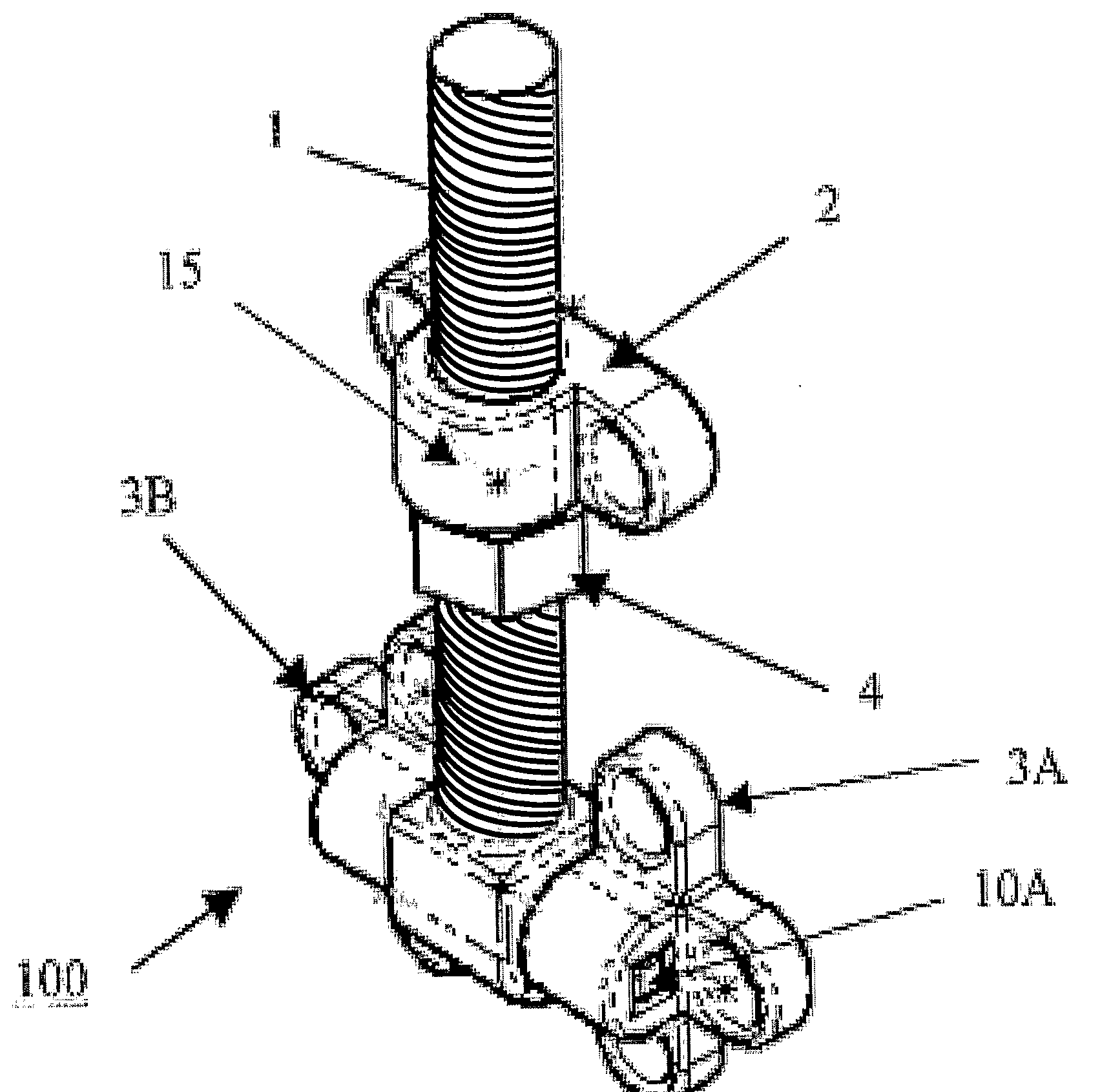
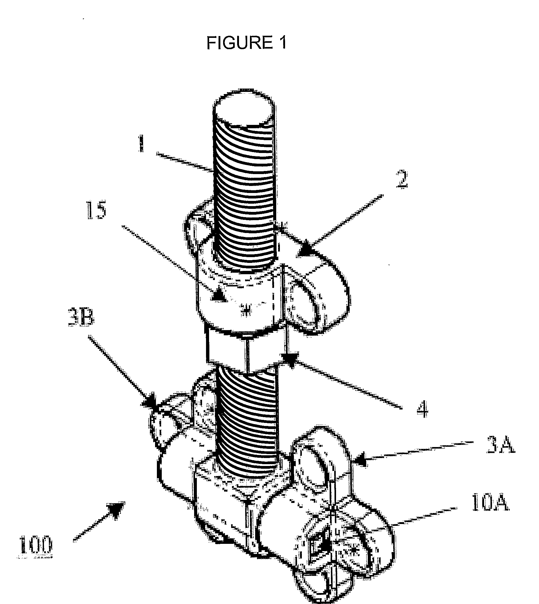
[0030]The present invention relates to a distraction device for facilitating both vertical and angular bone regeneration, particularly in the oral cavity.

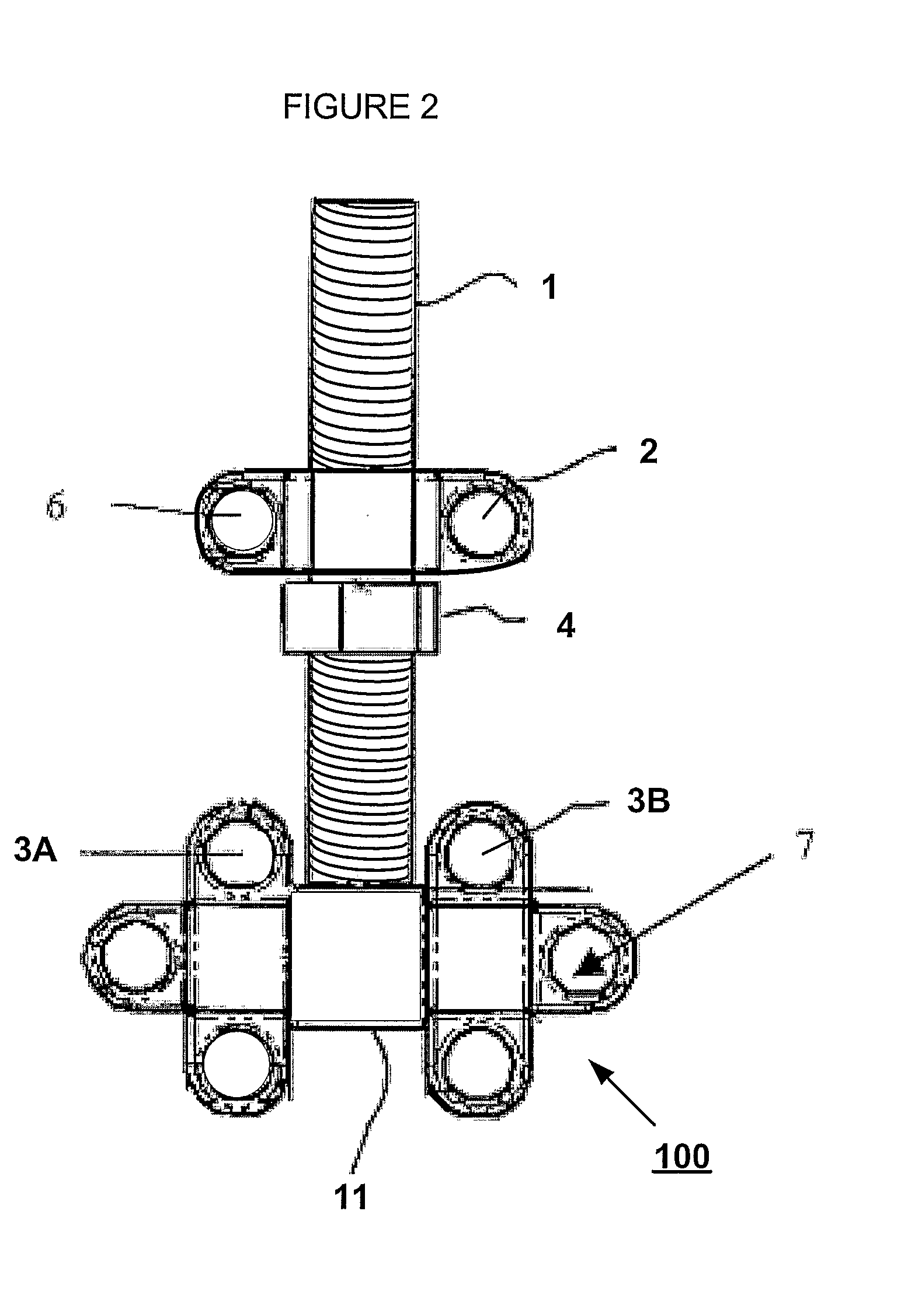
[0031]FIGS. 1, 2, 3, and 6 depict an exemplary distraction device 100 according to an embodiment of the present invention. The distraction device 100 includes a threaded rod 1, a threaded nut 4 disposed on the threaded rod 1, an upper transport plate 2, one or more lower transport plates 3A, 3B, and a connecting wedge 5. At one end of the threaded rod 1 is a connecting wedge housing 11 that includes an opening 12 shaped and sized to fit the connecting wedge 5, as described in detail below. In a preferred embodiment, the threaded rod 1 is composed of M0.5×3 standard isometric threads.

[0032]According to an embodiment of the present invention, the one or more lower transport plates 3A, 3B are adapted to be secured or attached to a healthy portion of a patient's bone and / or tissue surrounding the area of bone deficiency, referred to as...


PUM


Abstract

A distraction device that allows for an improved use of the existing process of distraction osteogenesis. The distraction device facilitates the displacement of a healthy portion of bone to a deficient area to enable bone and soft tissue growth in a fracture gap and allows for both vertical and angular bone regeneration.

Description

CROSS-REFERENCE TO RELATED APPLICATION[0001]This application claims the benefit of U.S. Provisional Application No. 60 / 668,818, filed Apr. 6, 2005. U.S. Provisional Application No. 60 / 668,818 is hereby incorporated herein by reference.FIELD OF THE INVENTION[0002]The present invention relates to a device for regenerating bone in a patient, particularly for use in a distraction osteogenesis method. Specifically, the present invention relates to an improved device that facilitates angled and vertical bone regeneration in the oral cavity, allowing for bone growth in a direction that is not necessarily vertical to the device.BACKGROUND OF THE INVENTION[0003]During the 1950's, Professor Gavril Ilizaroz revealed that controlled, mechanically applied tension stress on fractured bone produces successful regeneration of bone and soft tissue, a technique known today as distraction osteogenesis. Initially used for the treatment of fractures and non-unions, his methods have proven successful for...

Claims


Application Information

Patent Timeline
IPC IPC(8): A61C5/00A61B17/58
CPCA61B17/663
Inventor RANA, GRISHMAWHITE, DOROTHY
Owner STEVENS INSTITUTE OF TECHNOLOGY
Why Eureka
Try Eureka