Catheter for removal of an organized embolic thrombus

a catheter and embolic thrombus technology, applied in the field of catheters for removing organized embolic thrombuses, can solve the problems of reducing the effect of embolic material, reducing the invasiveness of surgical procedures, and reducing the risk of embolic complications

Active Publication Date: 2008-12-18
SURMODICS MD LLC
View PDF93 Cites 165 Cited by
  • Summary
  • Abstract
  • Description
  • Claims
  • Application Information

AI Technical Summary

Benefits of technology

[0007]The general purpose of the present invention is to provide a catheter for removal of an organized embolic thrombus and method of use. The present invention consist of three main parts: (a) a capture / delivery sheath; (b) a capture sleeve of mesh attached to a tube; and (c) a grasping mechanism attached to another tube which is central to the other two components. Other structures in the form of manifolds attach to such tubes to control the relative positions of the a capture / delivery sheath, the capture sleeve, and the grasping mechanism. Preferably, the invention is used with a 0.014″ distal occlusion balloon guidewire (Guard Dog®) of the previously referenced patent application Ser. No. 11 / 581,613 or with another suitable pulling device, such as by the inventors or others. The inflatable balloon of the distal occlusion balloon guidewire is advanced past the debris, the balloon is inflated, and the balloon is retracted toward the present invention (analogous to a Fogarty procedure except that a Fogarty procedure uses a surgical opening to withdraw the material). The present invention provides a procedure for the successful capture of the debris. The present invention is introduced into the vasculature to the site of embolic thrombus material, also referred to herein as debris, and then telescoped appropriately along the length of the invention. The capture sleeve is advanced and automatically deployed outwardly beyond the capture / delivery sheath. The grasping mechanism is advanced and automatically deployed outwardly beyond the capture sleeve. In the anticipated procedure, the balloon of the distal occlusion balloon guidewire is inflated and used to pull the debris into the outwardly deployed serrated fingers of the grasping mechanism. Both the serrated fingers of the grasping mechanism and the inflated balloon of the distal occlusion balloon guidewire are pulled into the capture sleeve. Then, the inflatable balloon of the distal occlusion balloon guidewire is either advanced out of the capture sleeve or deflated. At this point, the capture / delivery sheath is advanced over the capture sleeve and grasping mechanism to capture the embolic material therein. As the capture / delivery sheath is advanced, the embolic material (debris) is squeezed downwardly and forwardly past the serrated teeth of the fingers. The serrations help tear and reduce the embolic material to smaller pieces as it is finally contained within the fingers and capture sleeve when the capture / delivery sheath is deployed fully thereover. The capture sleeve and the grasping mechanism along with the captured embolic material is withdrawn proximally along the length of the capture / delivery sheath, whereupon the embolic material can be removed from the vasculature and detached from the grasping mechanism. Another capture sleeve and grasping mechanism can be introduced or the same capture sleeve and the grasping mechanism can be cleaned and reintroduced into the vasculature via the capture / delivery sheath if required.

Problems solved by technology

However, this surgical procedure is more invasive than an interventional procedure.
The debris is generally too tough for removal by mechanical thrombectomy catheters.
Fibrinolytic infusion is a viable technique but not guaranteed to be successful.
In addition, fibrinolytics are associated with adverse complications such as bleeding or hemorrhagic stroke.
First, the debris is not always easily found via fluoroscopy.
Second, stenting a thrombus does not remove it from the body and just ballooning and compressing the material will not guarantee that the debris would not further embolize distally.

Method used


Image

  • Catheter for removal of an organized embolic thrombus
  • Catheter for removal of an organized embolic thrombus
  • Catheter for removal of an organized embolic thrombus

Examples


Embodiment Construction

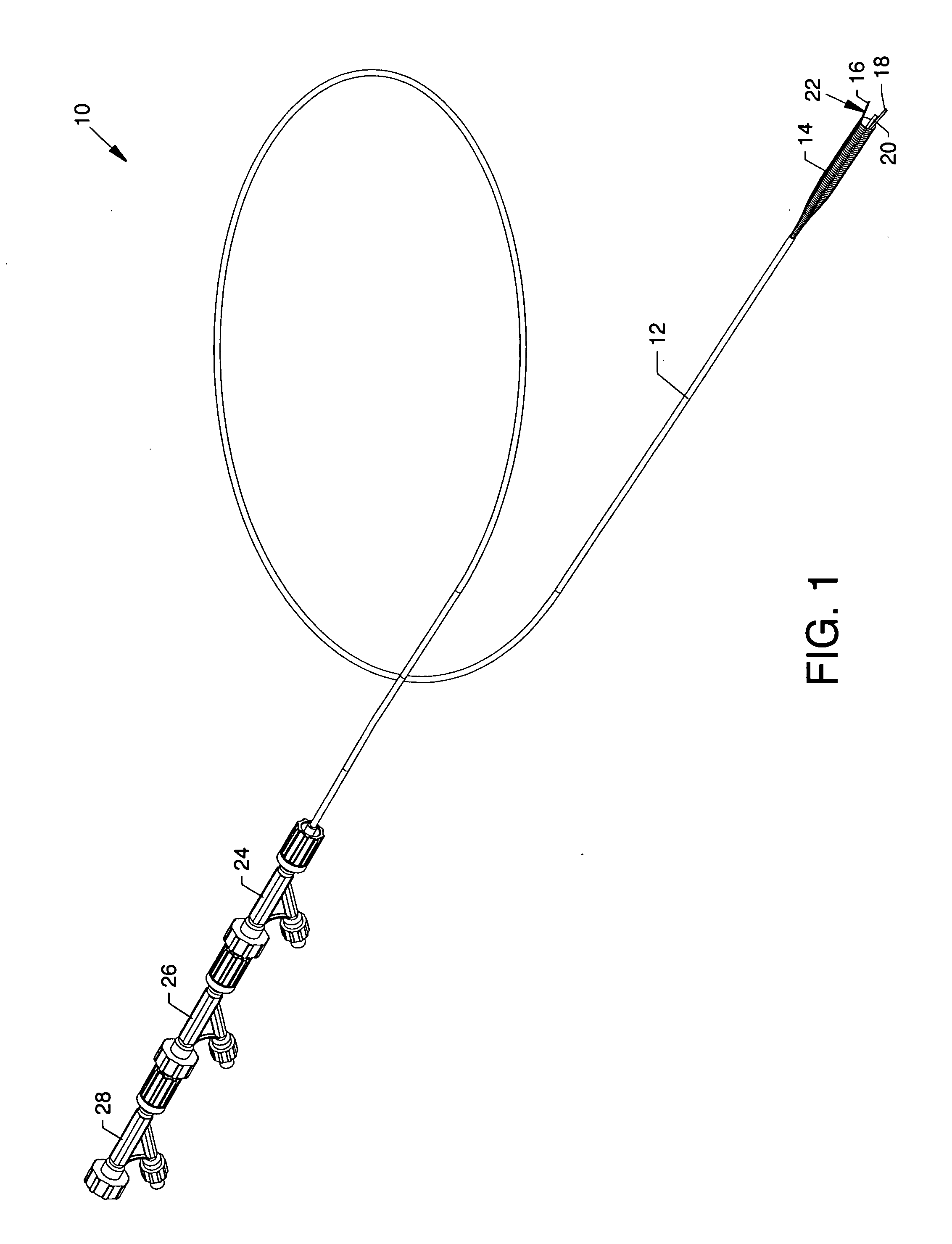
[0035]FIG. 1 is an isometric overview of the catheter 10 of the present invention for removal of an organized embolic thrombus. Fully or partially visible components of the present invention include a multiple function capture / delivery sheath 12, a distally located capture sleeve 14 shown in memory shape consisting of a nitinol and polymer mesh (shown in FIG. 3) extending distally from within the capture / delivery sheath 12, serrated fingers 16, 18 and 20 of a grasping mechanism 22 (FIG. 2) shown in memory shape, a capture / delivery sheath operator 24 in the form of a manifold attached to the proximal end of the capture / delivery sheath 12, a capture sleeve operator 26 in the form of a manifold in general longitudinal alignment with the capture / delivery sheath operator 24, and a grasping mechanism operator 28 in the form of a manifold in general longitudinal alignment with the capture sleeve operator 26.

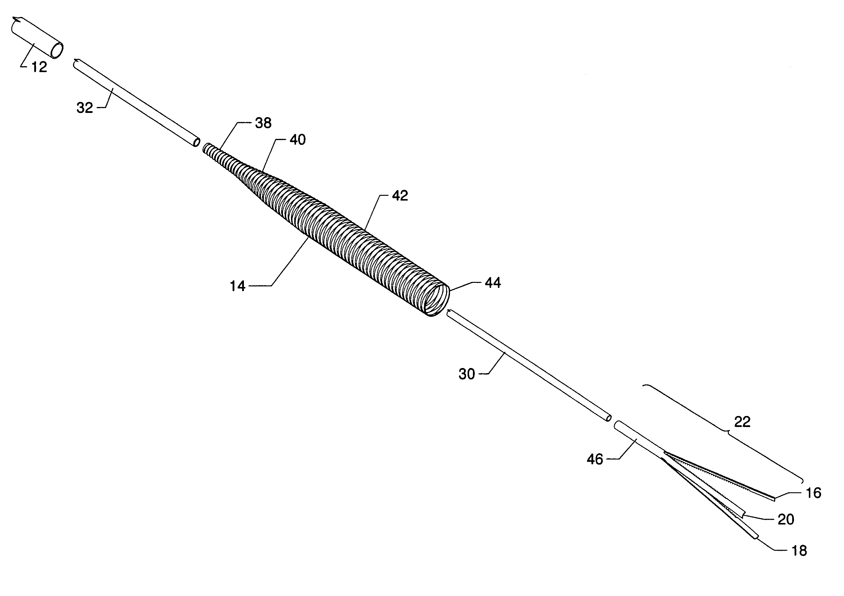
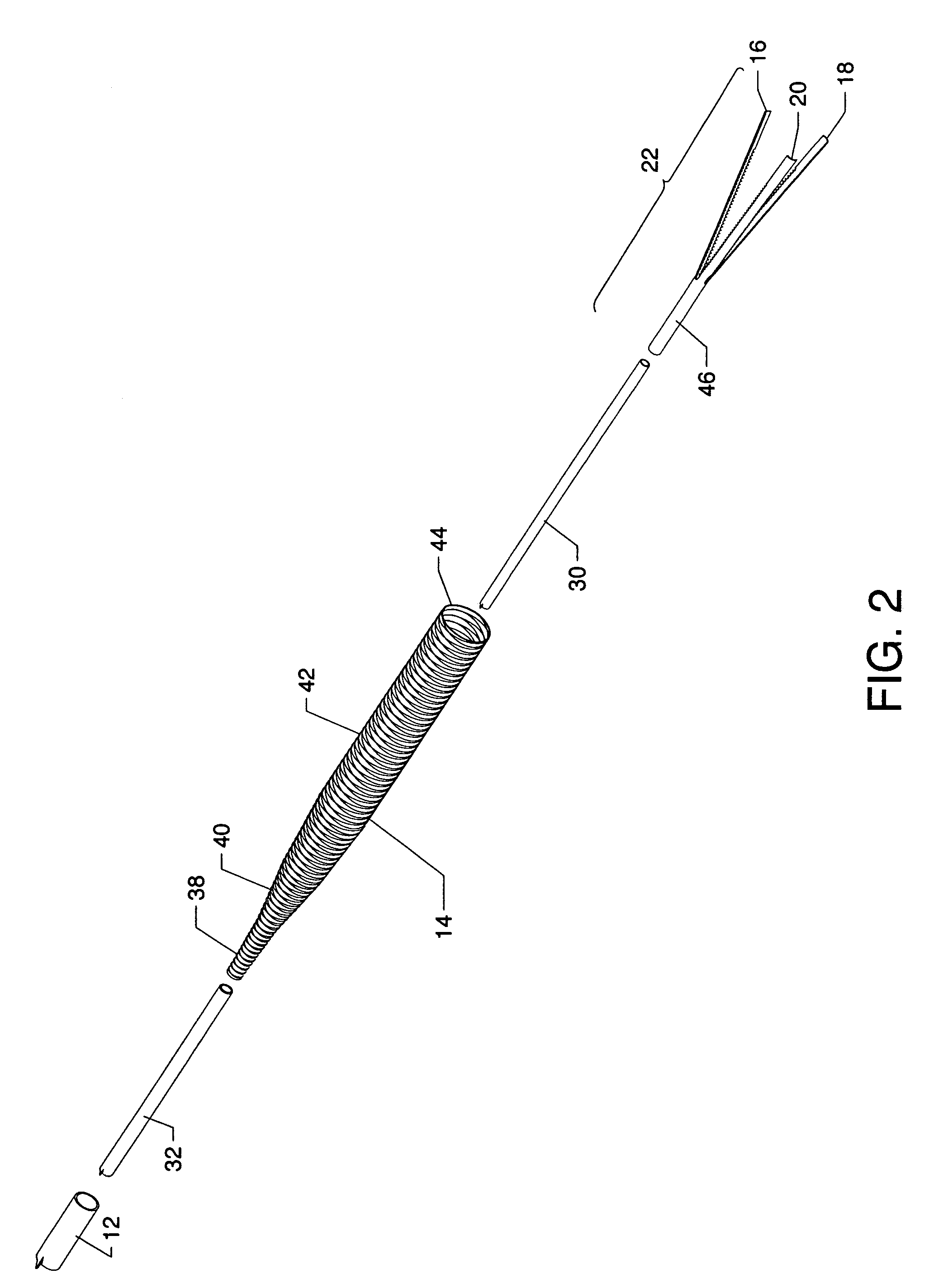
[0036]FIG. 2 is an exploded isometric view of the components located at the distal ...


PUM


Abstract

The general purpose of the present invention is to provide a catheter for removal of an organized embolic thrombus, preferably in conjunction with a distal occlusion balloon guidewire. The present invention consists of three main components including a capture/delivery sheath, a capture sleeve of mesh attached to a tube and a grasping mechanism attached to another tube which is central to the other components. Operative structures in the form of manifolds are connected to such components in order to manipulate and control the relative positions of the capture/delivery sheath, the capture sleeve and the grasping mechanism. An embolic thrombus is engaged by the deployable automatically expanding serrated fingers of a grasping mechanism in combination with a deployable automatically expanding mesh capture sleeve. The capture/delivery sheath is maneuvered to cause compression of the serrated fingers and of the mesh capture sleeve for subsequent removal of the embolic thrombus.

Description

CROSS REFERENCES TO RELATED APPLICATIONS[0001]This application claims priority from the earlier filed U.S. Provisional Application No. 60 / 934,268 filed Jun. 12, 2007, entitled “Catheter for Removal of Organized Embolic Thrombus”, and is hereby incorporated into this application by reference as if fully set forth herein.[0002]This patent application is related to patent application Ser. No. 11 / 581,613 filed on Oct. 16, 2006, entitled “Occlusive Guidewire System Having an Ergonomic Handheld Control Mechanism Prepackaged in a Pressurized Gaseous Environment and a Compatible Prepackaged Torqueable Kink-Resistant Guidewire With Distal Occlusive Balloon”, which is pending. The prior application is hereby incorporated into this application by reference as if fully set forth herein.BACKGROUND OF THE INVENTION[0003]1. Field of the Invention[0004]Tough organized embolic thrombus found in the vasculature of the human body may evolve from various origins. A trial thrombus that forms and organiz...

Claims


Application Information

Patent Timeline
Patent Type & Authority Applications(United States)
IPC IPC(8): A61M29/00
CPCA61B17/22031A61B17/221A61B2017/00867A61B2017/22044A61B2017/22067A61M2025/1052A61F2002/011A61M25/005A61M25/0662A61M2025/0175A61B2017/22094A61F2/011
Inventor ANSEL, GARY M.BONNETTE, MICHAEL J.THOR, ERIC J.MORRIS, DAVID B.WEISEL, STEPHEN D.
Owner SURMODICS MD LLC
Why Eureka
Try Eureka