Air conditioning system

a technology of air conditioning system and air outlet, which is applied in the direction of heating types, domestic cooling apparatus, vehicle cleaning, etc., can solve the problems of inability to reliably prevent the penetration of dust and so on into the operator's cab, the air sent to the operator's cab is reduced, and the inside of the operator's cab cannot be sufficiently pressurized, so as to prevent the penetration of dust and the lik

Inactive Publication Date: 2008-12-25
KOMATSU LTD
View PDF5 Cites 11 Cited by
  • Summary
  • Abstract
  • Description
  • Claims
  • Application Information

AI Technical Summary

Benefits of technology

[0010]According to the invention, the air feed rate of the blower is controlled so as to make the inside pressure of the operator's cab higher than outside pressure, which enables it to pressurize the inside of the operator's cab with a specified volume of air required to maintain the inside of the operator's cab at higher pressure than outside pressure. By constantly maintaining the inside of the operator's cab at higher pressure than outside pressure, dust and the like can be prevented from penetrating into the operator's cab without fail. In addition, the air sent from the blower is distributed to the air outlet directed to the operator and the air outlet undirected to the operator by the air distributing means and the volumes of air distributed to these air outlets are controlled by the air distribution controlling means based on...

Problems solved by technology

If the difference between an inside air temperature of the operator's cab and a preset temperature becomes small, the feed rate of air sent to the operator's cab decreases, so that the inside of the operator's cab cannot be sufficiently pressurized.
As a result, the penetration of dust and so on into the operator's cab cannot be reliably prevented.
However, the air conditioning control ...

Method used


Image

  • Air conditioning system
  • Air conditioning system
  • Air conditioning system

Examples


first embodiment

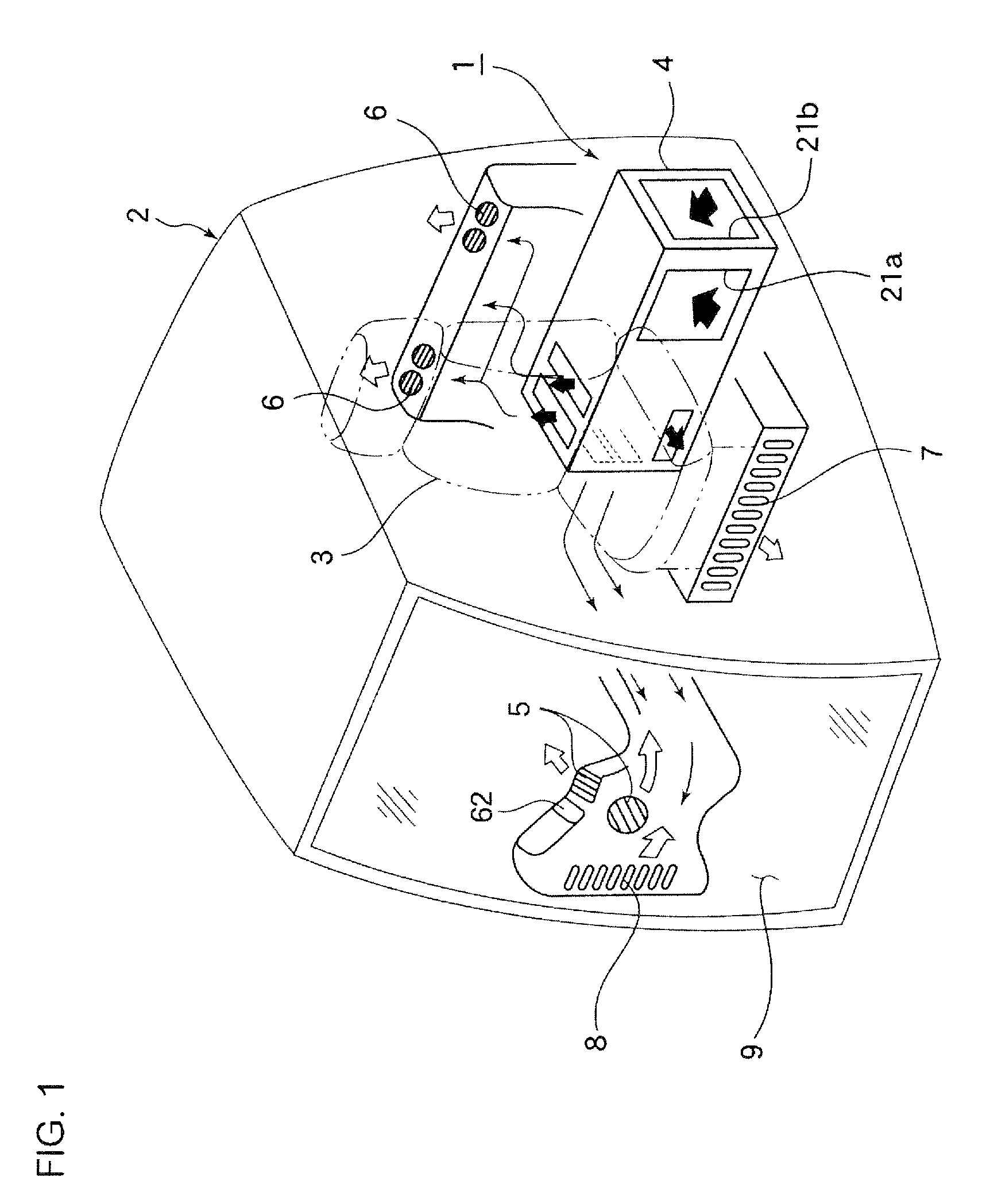
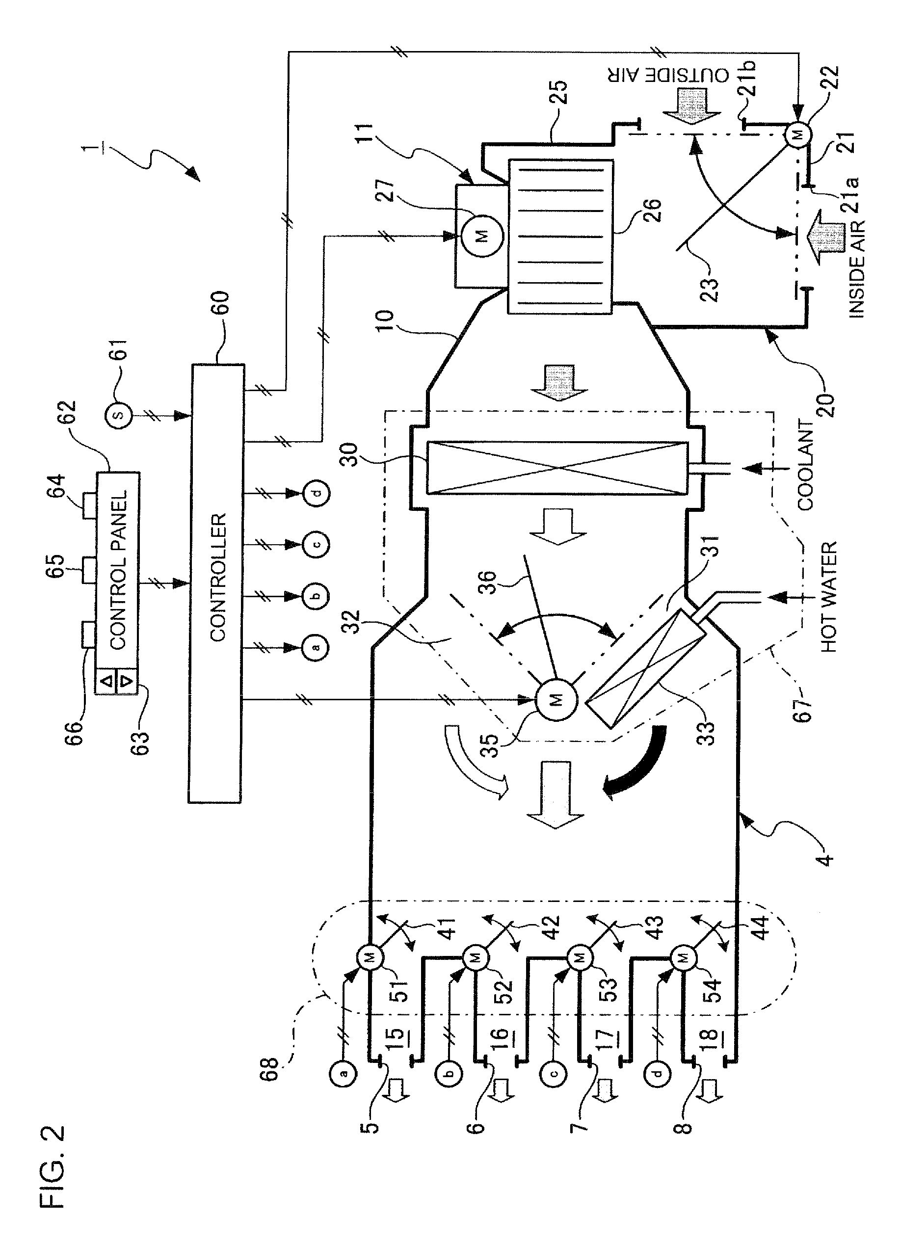
[0020]FIG. 1 is an overall external perspective view of an air conditioning system according to a first embodiment of the invention. FIG. 2 is a schematic system structural diagram of the air conditioning system of the first embodiment.

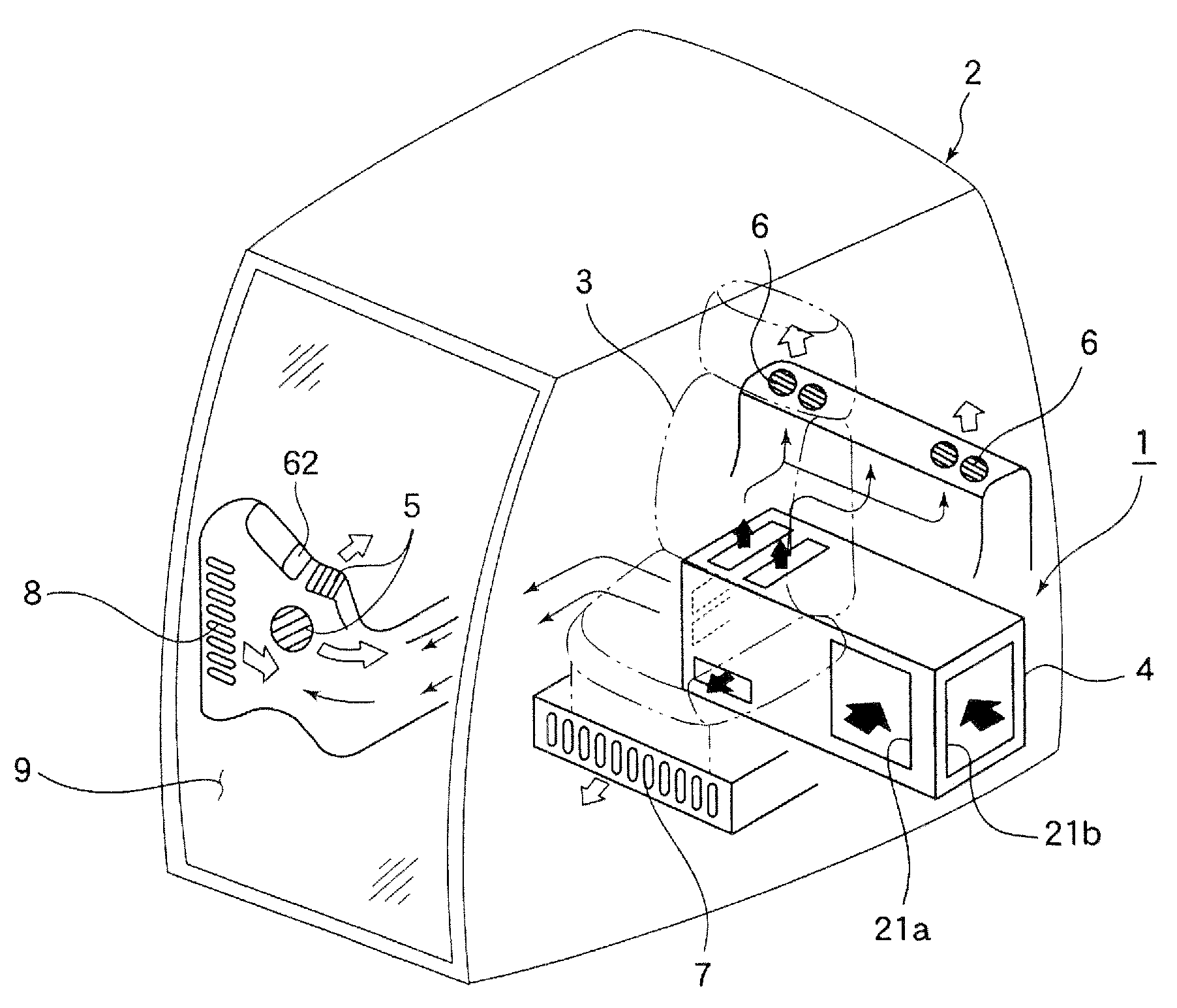
[0021]As illustrated in FIG. 1, the air conditioning system 1 of this embodiment has: a system body 4 placed behind an operator's seat 3 provided in an operator's cab 2; a face-level air outlet 5 arranged to direct air to the face or chest of the operator sitting on the operator's seat 3; a rear air outlet 6 arranged to direct air to the occiput and upper back of the operator sitting on the operator's seat 3; a foot-level air outlet 7 arranged to direct air to the feet of the operator sitting on the operator's seat 3; and a defroster air outlet 8 arranged to direct air to a front window pane 9 of the operator's cab 2. The face-level air outlet 5, rear air outlet 6, foot-level air outlet 7, and defroster air outlet 8 are openings through which air is b...

second embodiment

[0065]FIG. 7 shows an overall external perspective view of an air conditioning system according to a second embodiment of the invention. FIG. 8 shows a schematic system structural diagram of the air conditioning system 1A of the second embodiment. In the second embodiment, those parts substantially equivalent or similar to the first embodiment are identified by the same reference numerals as in the first embodiment and a detailed explanation thereof is omitted. In the following description, the points different from the first embodiment will be mainly described.

[0066]The second embodiment is associated with an example where a dedicated pressurization air outlet (specialized air outlet for operator's cab pressurization) 70 is separately provided which is used exclusively for ejecting air to pressurize the inside of the operator's cab 2 when PRESSURIZATION mode is selected and this dedicated pressurization air outlet 70 assumes the same role as of the defroster air outlet 8 of the fir...


PUM


Abstract

An air conditioning system includes a controller for controlling the feed rate of air from a blower such that the inside of the operator's cab is at higher pressure than outside pressure when a pressurization mode for pressurizing the inside of the operator's cab is selected, a branch duct opening/closing damper device is provided for distributing the air from the blower to an air outlet directed to an operator and an air outlet undirected to the operator (i.e., a defroster air outlet). Further, the controller controls the branch duct opening/closing damper device such that the air is ejected from the air outlet directed to the operator in such a volume that makes the operator have comfortable cool or warm feeling whereas the remaining volume of air is ejected from the defroster air outlet, when the difference between the inside air temperature of the operator's cab and a preset temperature becomes small.

Description

TECHNICAL FIELD[0001]The present invention relates to an air conditioning system capable of maintaining the inside of an operator's cab at higher pressure than outside pressure.BACKGROUND ART[0002]Work vehicles such as hydraulic excavators and bulldozers are often used in dust-laden work environments. The work vehicles of this type are therefore required to have the function of preventing the penetration of dust and so on into the operator's cab through the gaps around the door or window panes. One known means that implements such a function makes use of the air conditioning system installed in the work vehicle. Specifically, air introduced from an outside air inlet is sent to the operator's cab to pressurize the inside thereof, thereby maintaining the inside of the operator's cab at higher pressure than outside pressure. This prevents dust and so on from penetrating into the operator's cab through the gaps around the door or window panes.[0003]In the conventional air conditioning s...

Claims


Application Information

Patent Timeline
IPC IPC(8): B60H1/32F25B29/00F25D17/06B60S1/54F24F3/02
CPCB60H1/00378B60H1/00842
Inventor NAGAMI, KOUJIMIYAZAKI, MASAMICHI
Owner KOMATSU LTD
Why Eureka
Try Eureka