Method of Controlling Arc Welding and Welding Apparatus

a control method and welding technology, applied in the direction of welding/cutting media/materials, welding apparatus, manufacturing tools, etc., can solve problems such as arcing stability

Active Publication Date: 2008-12-25
PANASONIC CORP
View PDF6 Cites 56 Cited by
  • Summary
  • Abstract
  • Description
  • Claims
  • Application Information

AI Technical Summary

Benefits of technology

[0006]The present invention relates to a method of controlling arc welding which alternately repeats a short-circuiting period and an arcing period while feeding a welding wire. In this method, a wire feeding speed is decreased to a lower speed than a base feeding speed in the short-circuiting period, and the wire feeding speed is increased to the base feeding speed in the arcing period. During the arcing period, a welding current is increased to a predetermined peak value by means of current control from the start of arcing to a first predetermined time, the welding current is then supplied with a welding voltage, of which a source voltage is controlled constant, from the first predetermined time to a second predetermined time, and the welding current is decreased thereafter to a base current of a value lower than the peak current by means of current control from the second predetermined time until the end of the arcing period.

Problems solved by technology

In the conventional method of controlling arc welding described above, there is a problem in arcing stability because of the presence of the normal short-circuiting period from time t1 to t2 and another short-circuiting period from time t3 to t5, which is much longer than the normal period.

Method used


Image

  • Method of Controlling Arc Welding and Welding Apparatus
  • Method of Controlling Arc Welding and Welding Apparatus
  • Method of Controlling Arc Welding and Welding Apparatus

Examples


first exemplary embodiment

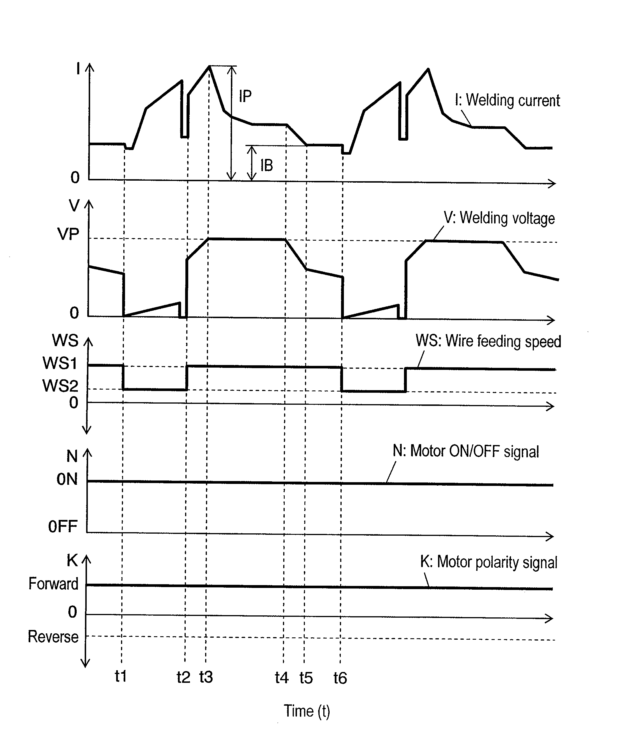
[0042]FIG. 1 shows a method of controlling arc welding according to a first exemplary embodiment of this invention. Shown in the figure are welding current I, welding voltage V, wire feeding speed WS, motor ON / OFF signal N for directing to turn on and off of a wire feeding motor, and motor polarity signal K for regulating a rotating direction of the wire feeding motor, as they change with the time respectively.

[0043]Welding current I is increased at a predetermined gradient by means of current control in a short-circuiting period from time t1 to time t2. At the same time, wire feeding speed WS is decreased from base feeding speed WS1 to another speed WS2. Welding current I is decreased steeply immediately before the end of the short-circuiting period by detecting a tapering of melted welding wire.

[0044]From time t2 to time t3 in an arcing period, welding current I is increased at a predetermined gradient by means of current control until it reaches peak current IP of a value determi...

second exemplary embodiment

[0066]FIG. 7 shows a method of controlling arc welding according to a second exemplary embodiment of this invention. Shown in this figure are welding current I, welding voltage V, wire feeding speed WS, motor ON / OFF signal N for directing to turn on and off of a wire feeding motor, and motor polarity signal K for regulating a rotating direction of the wire feeding motor, as they change with the time respectively.

[0067]This method differs from that of the first exemplary embodiment in respect that wire feeding speed WS is brought to zero, that is, feeding of the wire is stopped during a short-circuiting period from time t1 to time t2. All other functions remain analogous to the first exemplary embodiment (refer to FIG. 1).

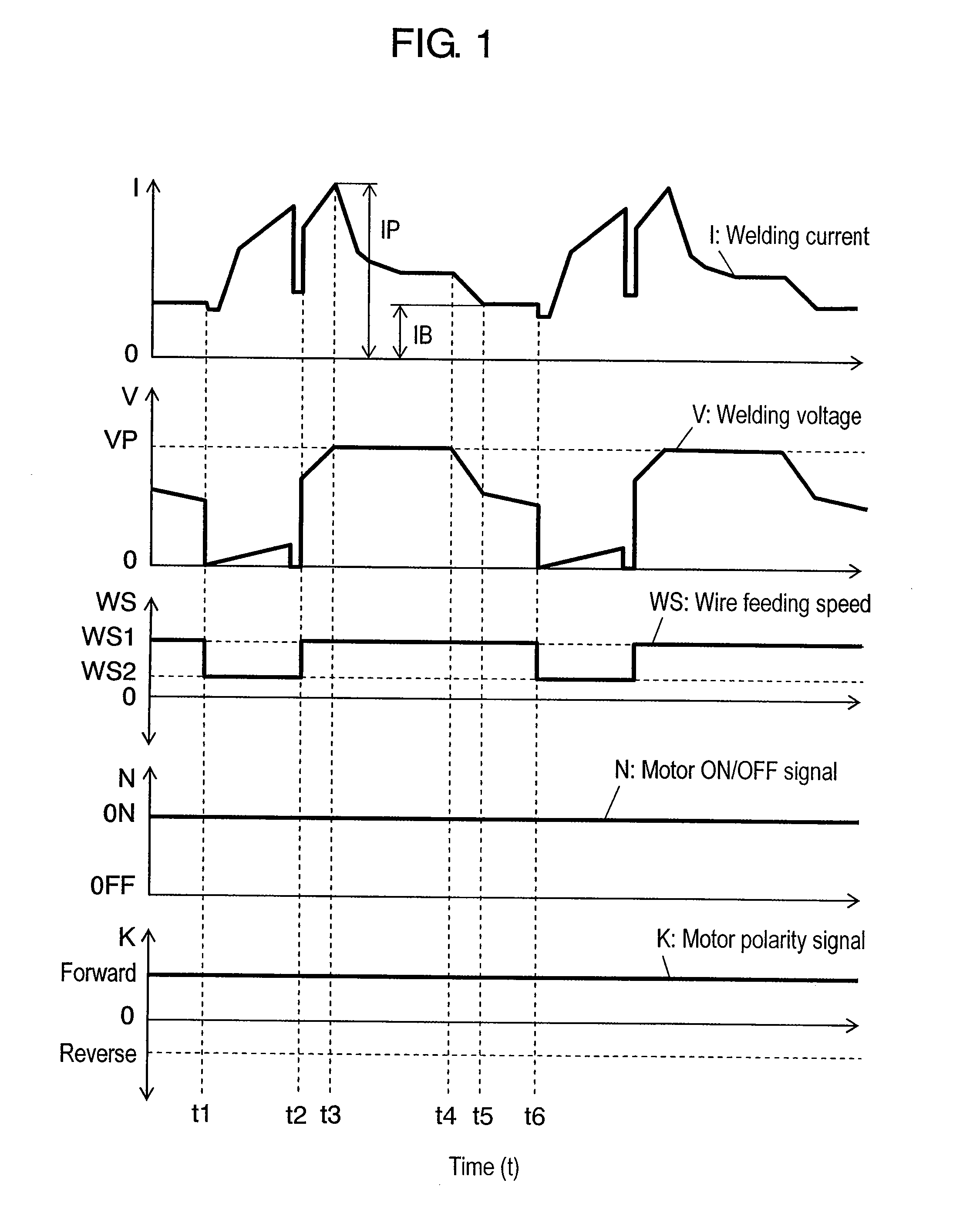
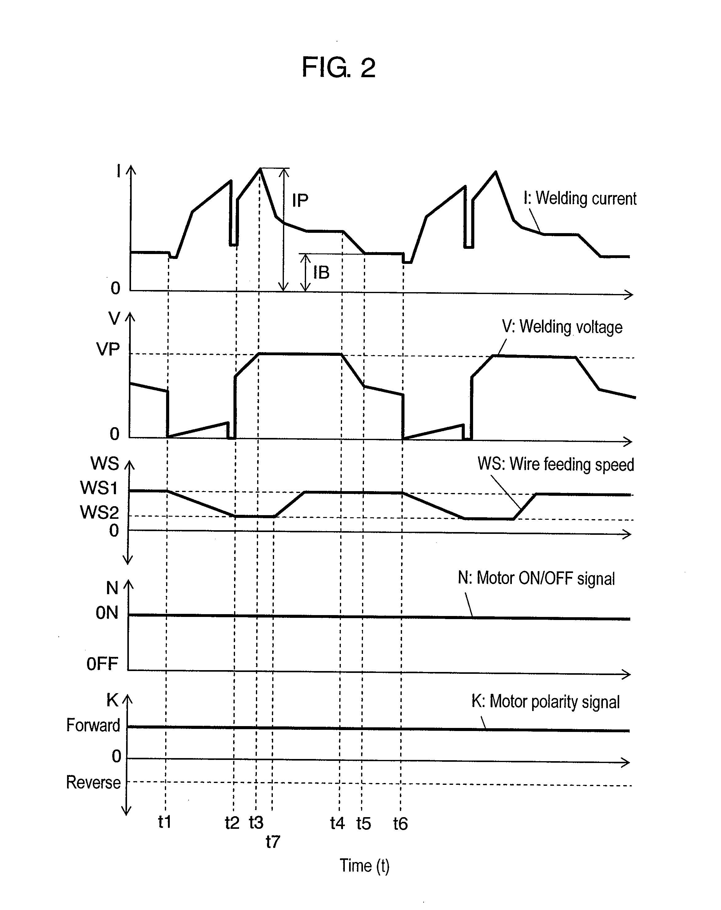
[0068]Wire feeding speed WS can be changed at a predetermined gradient in the same manner as the first exemplary embodiment (refer to FIGS. 2 and 3). In addition, a timing of changing wire feeding speed WS can be delayed as well (refer to FIG. 2).

[0069]It is also po...

third exemplary embodiment

[0072]FIG. 8 shows a method of controlling arc welding according to a third exemplary embodiment of this invention. The figure shows welding current I, welding voltage V, wire feeding speed WS, motor ON / OFF signal N for directing to turn on and off of a wire feeding motor, and motor polarity signal K for regulating a rotating direction of the wire feeding motor, as they change with the time respectively.

[0073]This method differs from that of the first exemplary embodiment in respect that wire feeding speed WS is reversed to a backward direction during a short-circuiting period from time t1 to time t2. All other functions remain analogous to the first exemplary embodiment (refer to FIG. 1).

[0074]Wire feeding speed WS can be changed at a predetermined gradient in the same manner as the first exemplary embodiment (refer to FIGS. 2 and 3). In addition, a timing of changing wire feeding speed WS can be delayed as well (refer to FIG. 2). It is also possible to offset a decreased amount an...


PUM

PropertyMeasurementUnit
peak current IPaaaaaaaaaa
speedaaaaaaaaaa
feeding speedaaaaaaaaaa

Abstract

A wire feeding speed is decreased to a level lower than a base wire feeding speed in a short-circuiting period, and set to the base wire feeding speed in an arcing period. During the arcing period, a welding current is increased to a predetermined peak value by means of current control from the start of arcing to a first predetermined time, the welding current is then supplied with a welding voltage, a source voltage of which is controlled constant, from the first predetermined time to a second predetermined time, and the welding current is decreased to a predetermined base current by means of current control from the second predetermined time until the end of the arcing period.

Description

TECHNICAL FIELD[0001]The present invention relates to a method of controlling arc welding which alternately repeats a short-circuiting period and an arcing period while feeding a welding wire, and a welding apparatus of the same.BACKGROUND ART[0002]FIG. 9 shows a conventional method of controlling arc welding. Welding voltage Vw, welding current Iw, speed setting signal Fr for feeding a wire, and feeding speed Fs of a tip of the wire are shown in the figure, as they change with the time respectively. A short-circuiting period Ts between t1 and t2 is shorter than predetermined time period Tt, and signal Fr remains at a level of Ffr for setting forward feeding of the wire, which hence maintains feeding of the wire at a speed of Ffs. The wire is fed continuously at the same speed Ffs in the succeeding arcing period Ta between t2 and t3.[0003]Signal Fr still remains at the level of Ffr in a short-circuiting period commencing from time t3, and the wire is fed at the speed of Ffs until ti...

Claims


Application Information

Patent Timeline
Patent Type & Authority Applications(United States)
IPC IPC(8): B23K9/073B23K9/10B23K9/09
CPCB23K9/0735B23K9/092B23K9/125
Inventor FUJIWARA, JUNJIMUKAI, YASUSHIKAWAMOTO, ATSUHIROKOWA, MASARU
Owner PANASONIC CORP
Why Eureka
Try Eureka