[0010]The landing gear assembly of the present invention overcomes the above-discussed disadvantages of prior art landing gear assemblies by providing a landing gear assembly with a two-speed or two-torque gear mechanism that has a simplified, reduced cost construction and is entirely contained in a leg housing of the landing gear assembly. This enables the landing gear assembly of the present invention to be economically manufactured and to be readily used with various different types of trailer configurations.
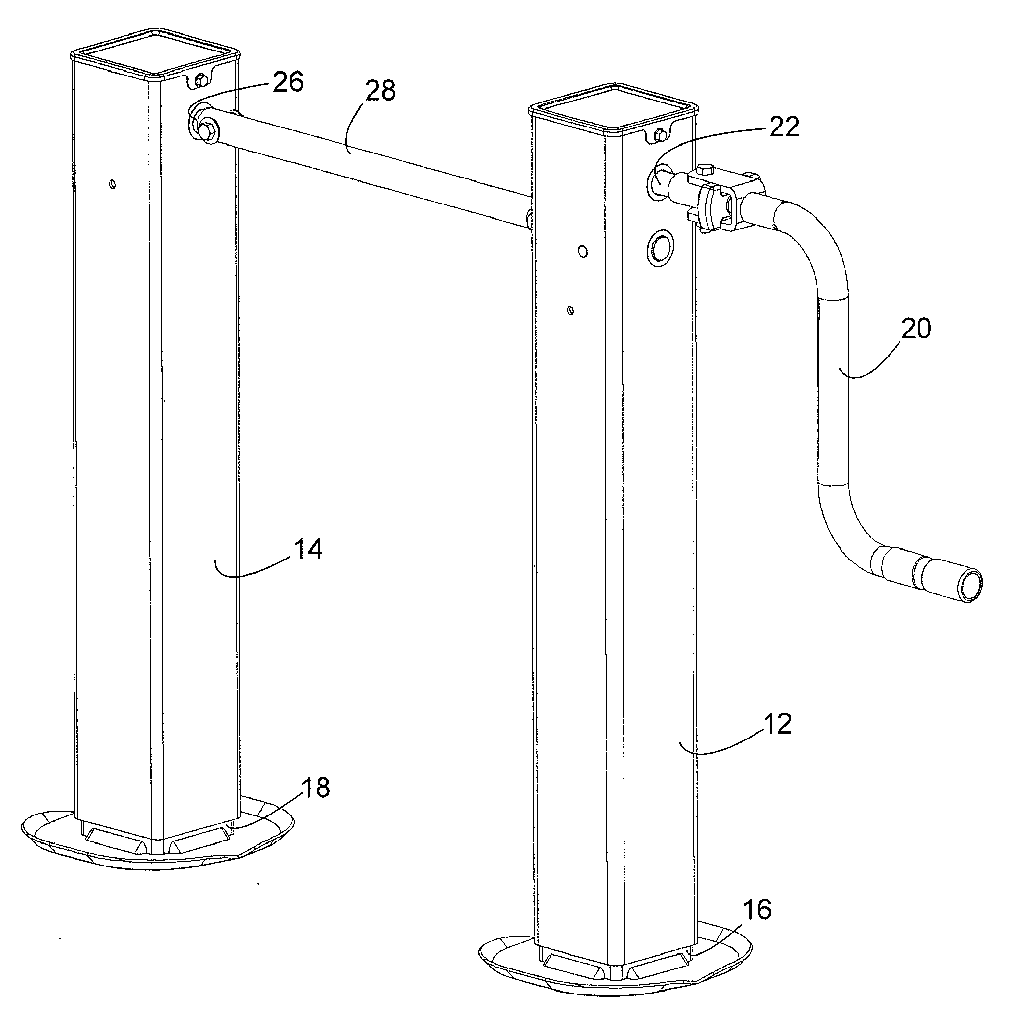
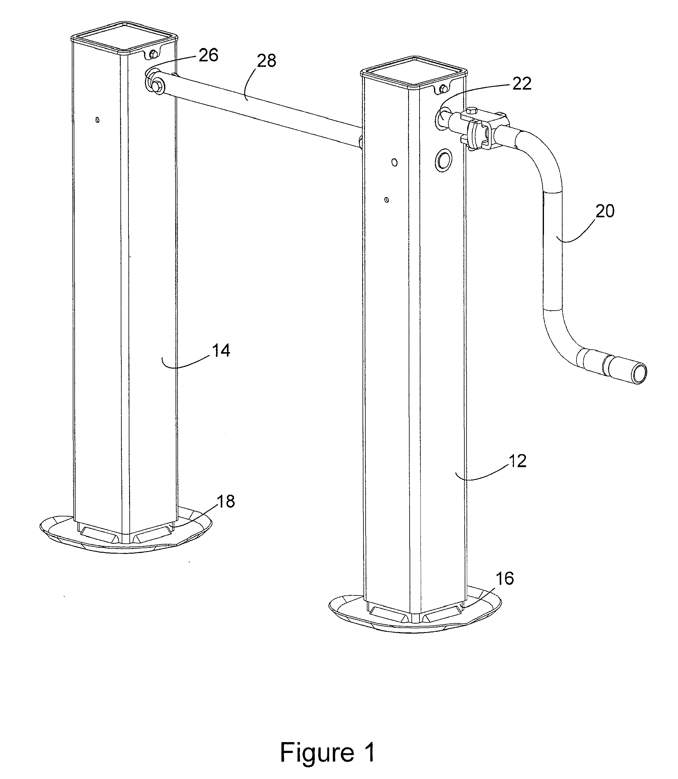
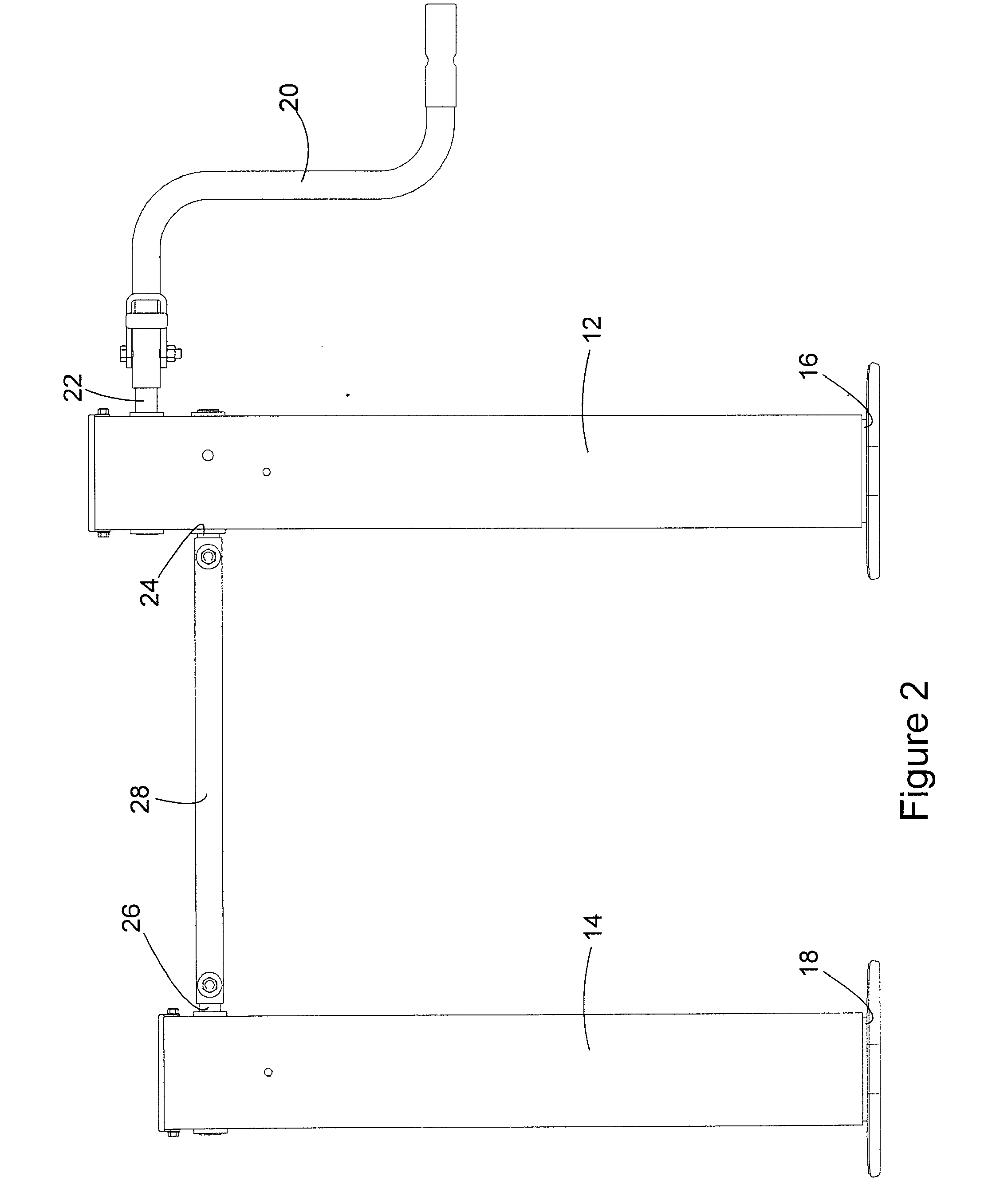
[0011]The landing gear assembly is provided in a master leg and slave leg arrangement, where the power for lifting and lowering the
truck trailer is provided by the master leg, as is conventional. An input shaft enters one side of the leg housing of the master leg and an output shaft exits the opposite side of the leg housing. The output shaft extends across the landing gear assembly to drive a
bevel gear mechanism in the slave leg. The
bevel gear mechanism extends and retracts the length of the slave leg to match the extension and retraction of the master leg. The novel gearing mechanism of the invention is comprised of only an input shaft and an output shaft, and does not require any other additional shafts for supporting gearing of the mechanism. Reducing the number of shafts required by the gearing mechanism reduces the cost of manufacturing the gearing mechanism.
[0014]The gear mechanism of the invention also includes an output gear that is secured stationary to the output shaft inside the leg housing, a first driven gear that is secured stationary to the output shaft inside the leg housing, and a second driven gear that is secured stationary to the output shaft inside the leg housing. In the preferred embodiment, the output gear, the first driven gear, and the second driven gear are all part of a one-piece gear element that is secured to the output shaft. This construction of the gear element further reduces the manufacturing cost of the landing gear apparatus. The output gear meshes directly with the
actuator input gear. The first driven gear meshes directly with the first drive gear and has a fewer number of gear teeth than the first drive gear. Thus, each rotation of the first drive gear with the input shaft drives the first driven gear and the output shaft in more than one rotation. The second driven gear meshes directly with the second drive gear and has a greater number of gear teeth than the second drive gear. Thus, each rotation of the input shaft and the second drive gear rotates the second driven gear and the output shaft in less than one rotation. However, the second drive gear imparts more torque to the second driven gear than does the first drive gear to the first driven gear.
[0015]A
clutch mechanism in the form of a
shear pin secured to the input shaft selectively secures the first drive gear or the second drive gear to the input shaft for rotation with the input shaft. When the first drive gear is secured to the input shaft, the second drive gear rotates freely on the input shaft. When the second drive gear is secured to the input shaft, the first drive gear rotates freely on the input shaft.
[0016]Moving the input shaft axially inwardly into the leg housing secures the first drive gear to the input shaft. Rotation of the input shaft with the first drive gear secured to the input shaft drives the first driven gear on the output shaft in rotation and in turn causes the
actuator assembly to lower and raise the leg column relative to the leg housing at a faster rate, depending on which direction the input shaft is turned by the manual
crank connected to the input shaft. Pulling the input shaft axially outwardly secures the second drive gear to the input shaft. Rotating the input shaft with the second drive gear secured to the input shaft causes the second drive gear to drive the second driven gear on the output shaft, which in turn drives the
actuator assembly to raise and lower the leg column relative to the leg housing at a slower rate, depending on the direction of rotation of the input shaft by the manual
crank. The gearing ratio of the second drive gear and the second driven gear, although moving the leg column more slowly relative to the leg housing, imparts greater torque to the output shaft and the actuator assembly, and thereby makes it easier to lift the weight of the trailer.
[0018]The novel gearing arrangement of the invention allows the landing gear apparatus to be constructed more compactly in a single leg housing, and more cost efficiently. The simplified gearing mechanism enables the input shaft, the output shaft, and a screw shaft of the actuator assembly to be positioned in a single plane, with these shafts being the only shafts contained in the leg housing. The reduced number of gears required by the gearing mechanism also reduces the cost of manufacturing the apparatus. Furthermore, the novel gear mechanism of the invention provides a landing gear apparatus with a two-speed operation where the gear mechanism is entirely contained in the landing gear assembly leg housing, removing the need for separate casing or housing for the gear mechanism.
