
Rear vehicle structure

a technology for rear vehicles and structures, applied in the direction of electric propulsion mounting, propulsion by batteries/cells, jet propulsion mounting, etc., can solve the problems of complex structure, increased weight, and multiple assembly procedures, and achieves high structural rigidity, increased user access difficulty, and cost reduction

Inactive Publication Date: 2008-12-25
NISSAN MOTOR CO LTD
View PDF23 Cites 16 Cited by
  • Summary
  • Abstract
  • Description
  • Claims
  • Application Information

AI Technical Summary

Benefits of technology

The present invention relates to a rear vehicle structure for automobiles that includes an electrical system unit. The rear vehicle structure includes extension members and cross members that are attached to the side members and rear suspension members of the vehicle. The electrical system unit is fixedly attached to the cross members, which are located above the rear suspension members. The rear vehicle structure may also include a luggage panel and a cover that provide enclosed space for the electrical system unit. The technical effects of the invention include improved safety, increased efficiency, and improved aesthetics.

Problems solved by technology

The vehicle structure described in Japanese Laid Open Patent Publication 2003-127907, however, is assembled from a plurality of frame members, thereby creating a complex structure requiring additional components that increase weight, add expense, and require multiple procedures to assemble.

Method used


Image

  • Rear vehicle structure
  • Rear vehicle structure
  • Rear vehicle structure

Examples


first embodiment

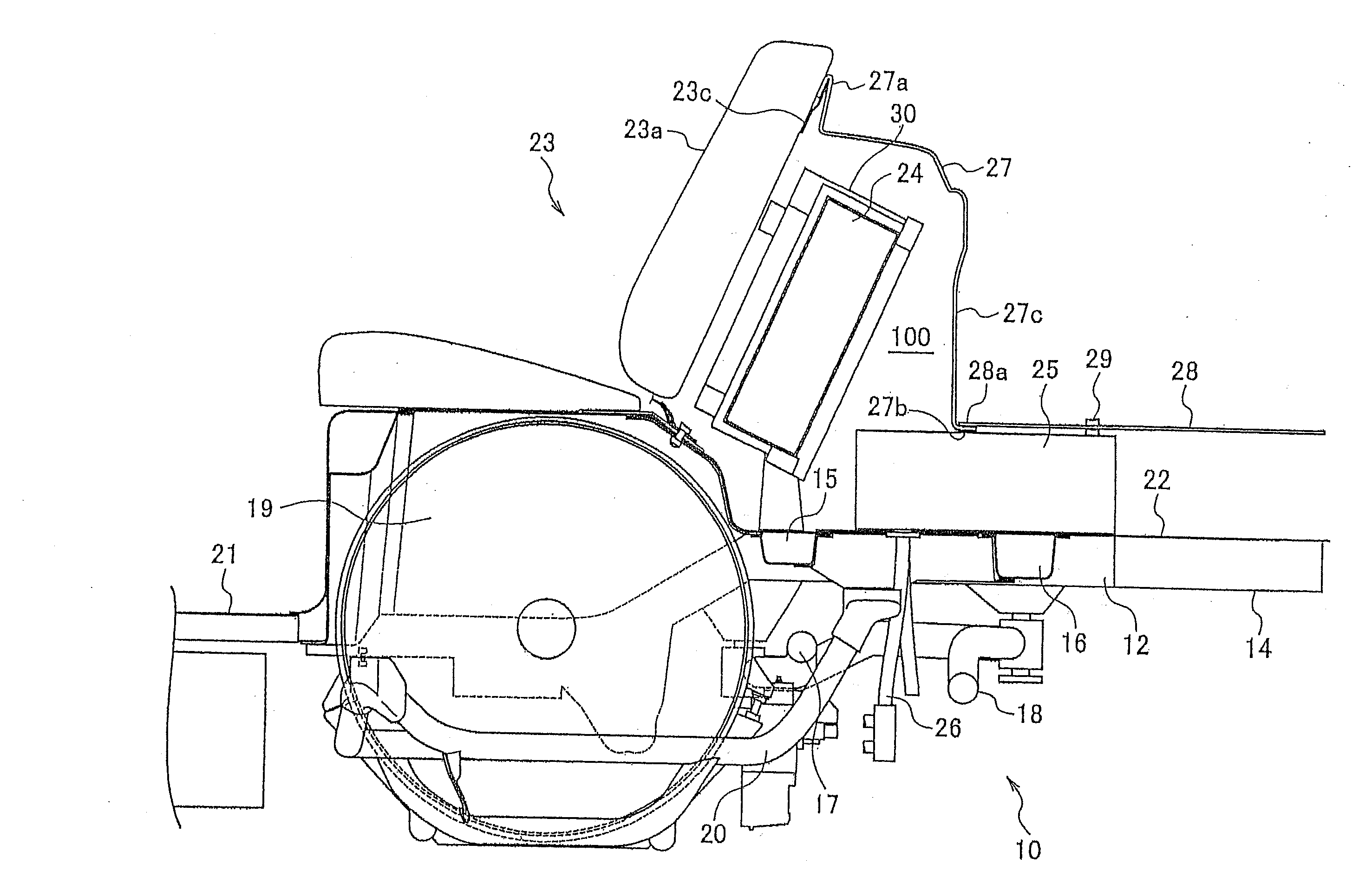
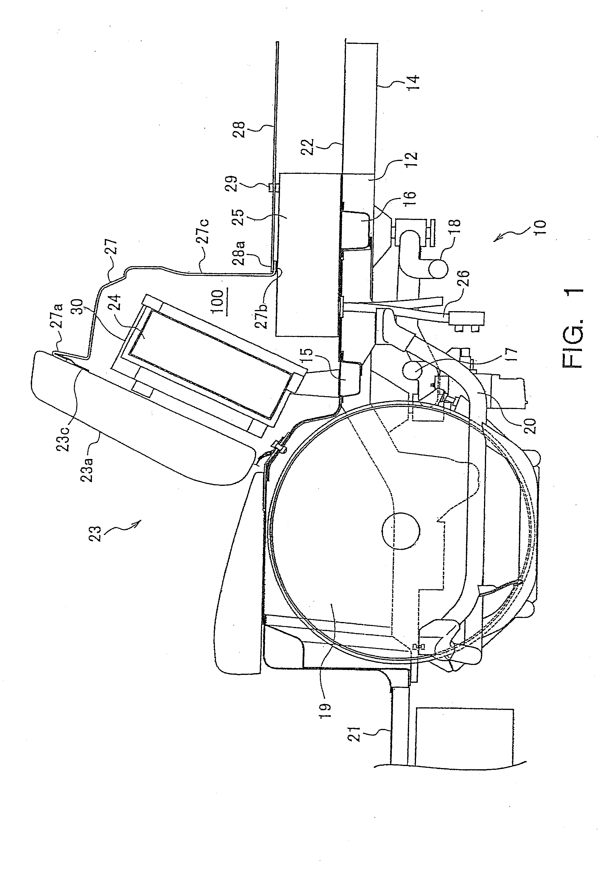
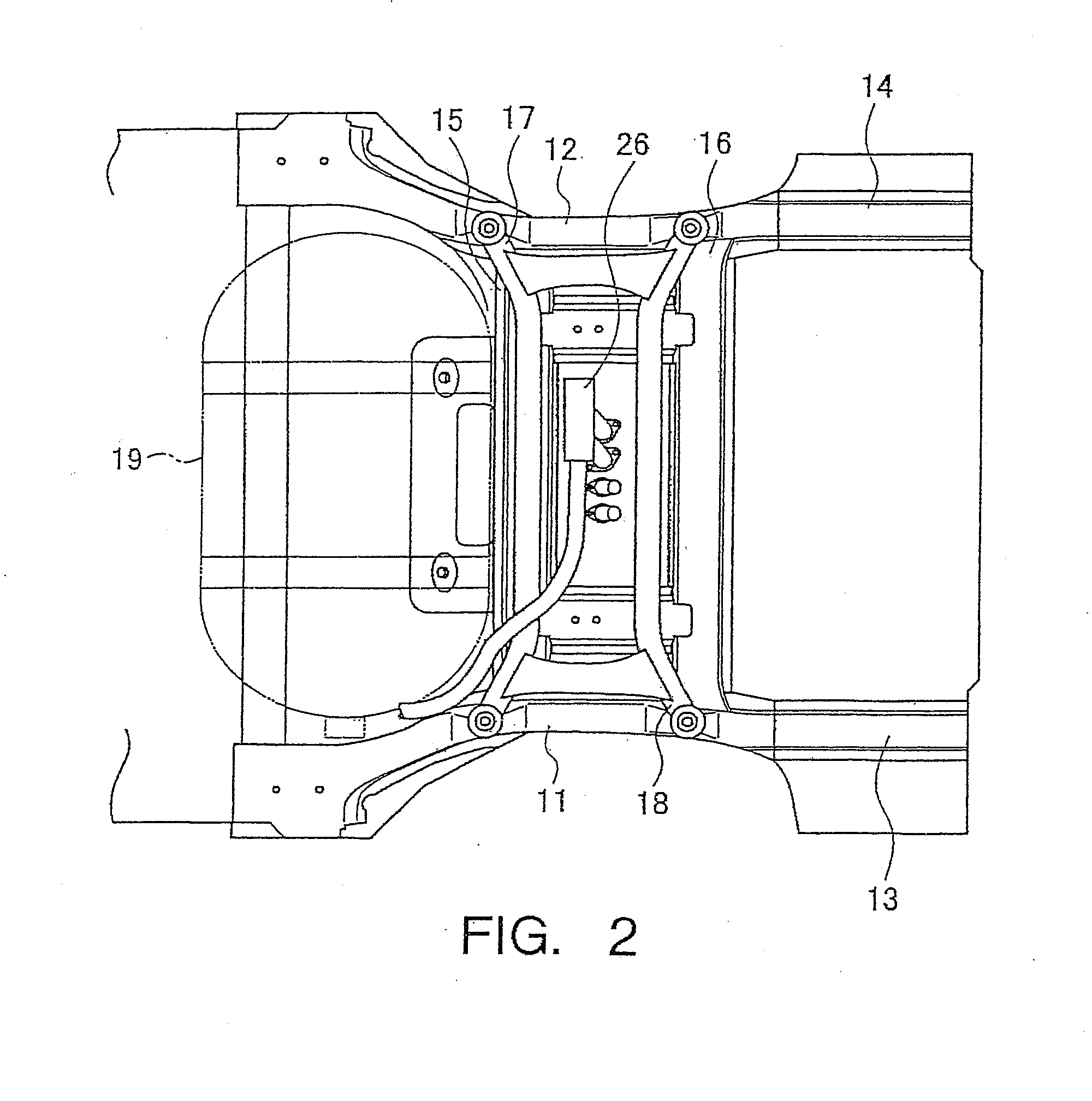
[0035]FIG. 1 and FIG. 2 describe a first embodiment of the rear vehicle structure 10, wherein FIG. 1 is an general cross section of the structures peripheral to a fuel tank 19 located in the rear portion of the vehicle 102, and FIG. 2 is a view of the FIG. 1 structure from below. FIG. 12 shows, generally, how the rear vehicle structure 10 is arranged within a typical vehicle 102. FIG. 1 provides a cross sectional view of a set of rear side members 11, 12 and a set of rear suspension members 17, 18 (and surrounding components) which are laid out along the center line of rear vehicle structure (and of the vehicle 102). Illustrational cross hatching has been omitted in FIG. 1. The following will describe the first embodiment of the invention with reference to FIG. 1 and FIG. 2.

[0036]The main components of rear vehicle structure 10 that are shown in FIGS. 1 and 2 are the rear side members 11 and 12 oriented along the lengthwise direction of the vehicle on the left and right sides, a set...

second embodiment

[0052]The following will describe a second embodiment of a vehicle rear structure according to the invention. FIG. 3 is a general cross section of the region surrounding to a fuel tank 19 installed in the rear portion of a vehicle. The element numbers in FIG. 3 refer to the same components identified by those numbers in FIG. 1. This second embodiment describes a rear vehicle structure 10A in which a secondary battery (second electrical system unit) 24 is placed on the rear cross members 15 and 16. A DC / DC converter (first electrical system unit) is not shown in FIG. 3.

[0053]In the second embodiment, the secondary battery 24 is installed with the leading or forward edge 31 of the battery case 30 placed over the cross sectional region of rear cross member 15, and trailing or rearward edge 32 is placed over the cross sectional region of rear cross member 16. As illustrated in the FIG. 4 (plan) view, the secondary battery 24 is secured to the vehicle 102 at two locations, one being at t...


PUM


Abstract

A rear vehicle structure has an electrical system unit, two side members, two extension parts, two cross members, a rear seat and a cover. The electrical system unit includes first and second electrical system units. Each extension part extends rearwardly from one of the rearward ends of one of the side members. The cross members are located above rear suspension members of the vehicle. The electrical system unit is fixedly attached to a top of at least one of the cross members. The rear seat is installed forward of the first electrical system unit. The second electrical system unit is located along a rearward surface of the rear seat. The cover is installed rearward of the second electrical system unit and has an upright panel that is oriented vertically to provide an enclosed space between a rearward surface of the second electrical system unit and the cover.

Description

CROSS-REFERENCE TO RELATED APPLICATION[0001]This application is a divisional application of U.S. patent application Ser. No. 11 / 090,035 filed on Mar. 28, 2005. The entire disclosures of U.S. patent application Ser. No. 11 / 090,035 is hereby incorporated herein by reference. The present application claims priority under 35 U.S.C. § 119 of Japanese Patent Application No. 2004-261285, filed on Sep. 8, 2004, the entire content of which is expressly incorporated by reference herein.BACKGROUND OF THE INVENTION[0002]1. Field of the Invention[0003]The invention relates to a rear vehicle structure; more specifically, to a structure for the rear portion of an electric automobile such as a fuel cell-powered automobile or like vehicle.[0004]2. Description of Related Art[0005]The rear end of a conventional electric automobile includes a sub-frame having crush-deforming parts (for example, side members) and bend-deforming parts (for example, fuel cell support members attached to the ends of the si...

Claims


Application Information

Patent Timeline
Patent Type & Authority Applications(United States)
IPC IPC(8): B62D21/00
CPCB60K15/063B60K15/07B62D25/2027B60L50/71B60L50/72Y02T90/40
Inventor HASHIMURA, TADAYOSHIMIZOTE, SHINICHIRONAGASAKA, SATOSHI
Owner NISSAN MOTOR CO LTD
Learn More