Light-emitting-diode drive circuit

a technology of light-emitting diodes and drive circuits, which is applied in the direction of electric variable regulation, process and machine control, instruments, etc., can solve the problems of high frequency noise and infeasibility of light-emitting-diodes drive circuits, and achieve the effect of reducing surge voltag

Inactive Publication Date: 2008-12-25
SHARP KK
View PDF9 Cites 41 Cited by
  • Summary
  • Abstract
  • Description
  • Claims
  • Application Information

AI Technical Summary

Benefits of technology

[0024]With this configuration, when one of the n′ lit-LED number control switches is turned on while the n light-emitting diodes connected in series are lit, the current path is bypassed, and thus the number of light-emitting diodes lit is controlled. Thus, it is possible to control light in n′+2 steps including those in which the n light-emitting diodes are all turned on and off. This makes it possible to control light emitted by a plurality of light-emitting diodes without the use of pulse signals.
[0028]In the light-emitting-diode drive circuit configured as described above, when the n light-emitting diodes connected in series are tuned on or off, the n light-emitting diodes connected in series may be turned on or off with the n′ lit-LED number control switches on a one-by-one basis or in units of two or three. Thus, it is possible to reduce a surge voltage that adversely affects the light-emitting-diode drive circuit and peripheral elements connected thereto as compared with the case where the light-emitting diodes are all turned on or off at the same time.
[0029]With the light-emitting-diode drive circuit according to the present invention, when one of the n′ (where n′ is any natural number equal to or greater than two but equal to or less than n) lit-LED-number control switches is turned on, how many of the n (where n is any natural number equal to or greater than two) light-emitting diodes connected in series are lit is controlled. Thus, it is possible to control light in n′+2 steps including those in which the n light-emitting diodes are all turned on and off. This makes it possible to control light emitted by the n light-emitting diodes without the use of pulse signals.

Problems solved by technology

In the conventional light-emitting-diode drive circuit that drives a plurality of light-emitting diodes connected in series, the series connection of the light-emitting diodes makes it impossible to turn off only one of the light-emitting diodes, with the result that all the light-emitting diodes are either turned on or turned off.
Disadvantageously, however, with the conventional light-control method described above, a circuit is additionally required that generates pulse signals for light control, and light-control pulse signals varying at relatively short intervals cause high-frequency noise to the light-emitting-diode drive circuit.
Another disadvantage is that when visible light communication or the like in which communication is achieved by the turning on and off of light-emitting diodes at such short intervals that it cannot be perceived by the human eye becomes common, such communication will suffer interference from the light-control method in which light control is achieved with a light-control pulse signal such as a PWM signal by the turning on and off of light-emitting diodes, and thus will become infeasible.

Method used


Image

  • Light-emitting-diode drive circuit
  • Light-emitting-diode drive circuit
  • Light-emitting-diode drive circuit

Examples


first embodiment

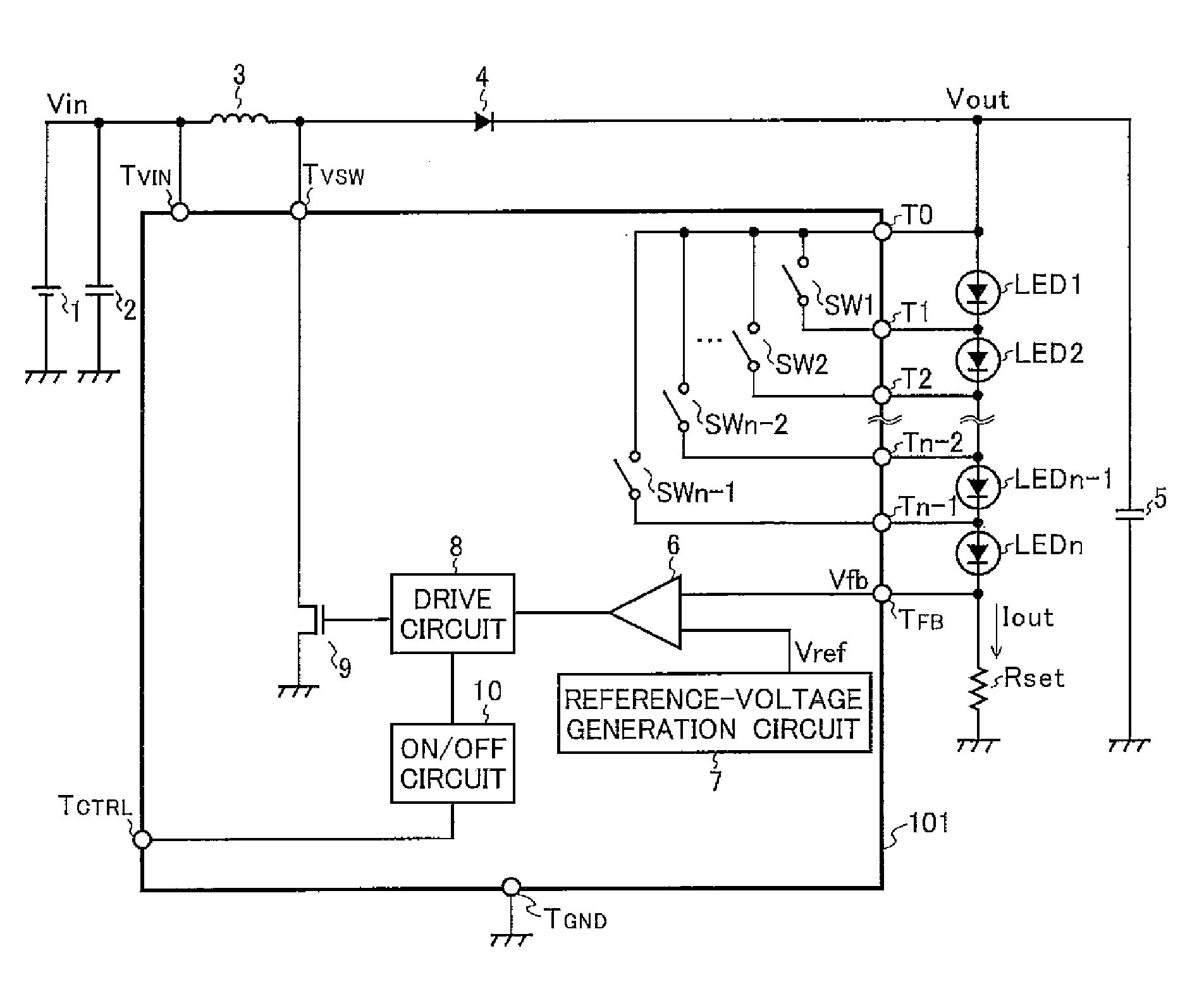
[0041]The light-emitting-diode drive circuit shown in FIG. 1 according to the invention differs from the conventional light-emitting-diode drive circuit shown in FIG. 10 in that the step-up chopper regulator IC 100 is replaced with a step-up chopper regulator IC 101. The step-up chopper regulator IC 101 differs from the step-up chopper regulator IC 100 in that it is additionally provided with: lit-LED-number control switches SW1 to SWn−1; a terminal T0 to which one ends of the lit-LED-number control switches are all connected; and terminals T1 to Tn−1 to which the other ends of the lit-LED-number control switches are respectively connected. The terminal T0 is connected to the anode of a light-emitting diode LED1; a terminal Tk is connected to the node between the cathode of a light-emitting diode LEDk and the anode of a light-emitting diode LEDk+1 (k is any natural number equal to or greater than one but equal to or less than n−1).

[0042]With this configuration, when one of the lit-L...

sixth embodiment

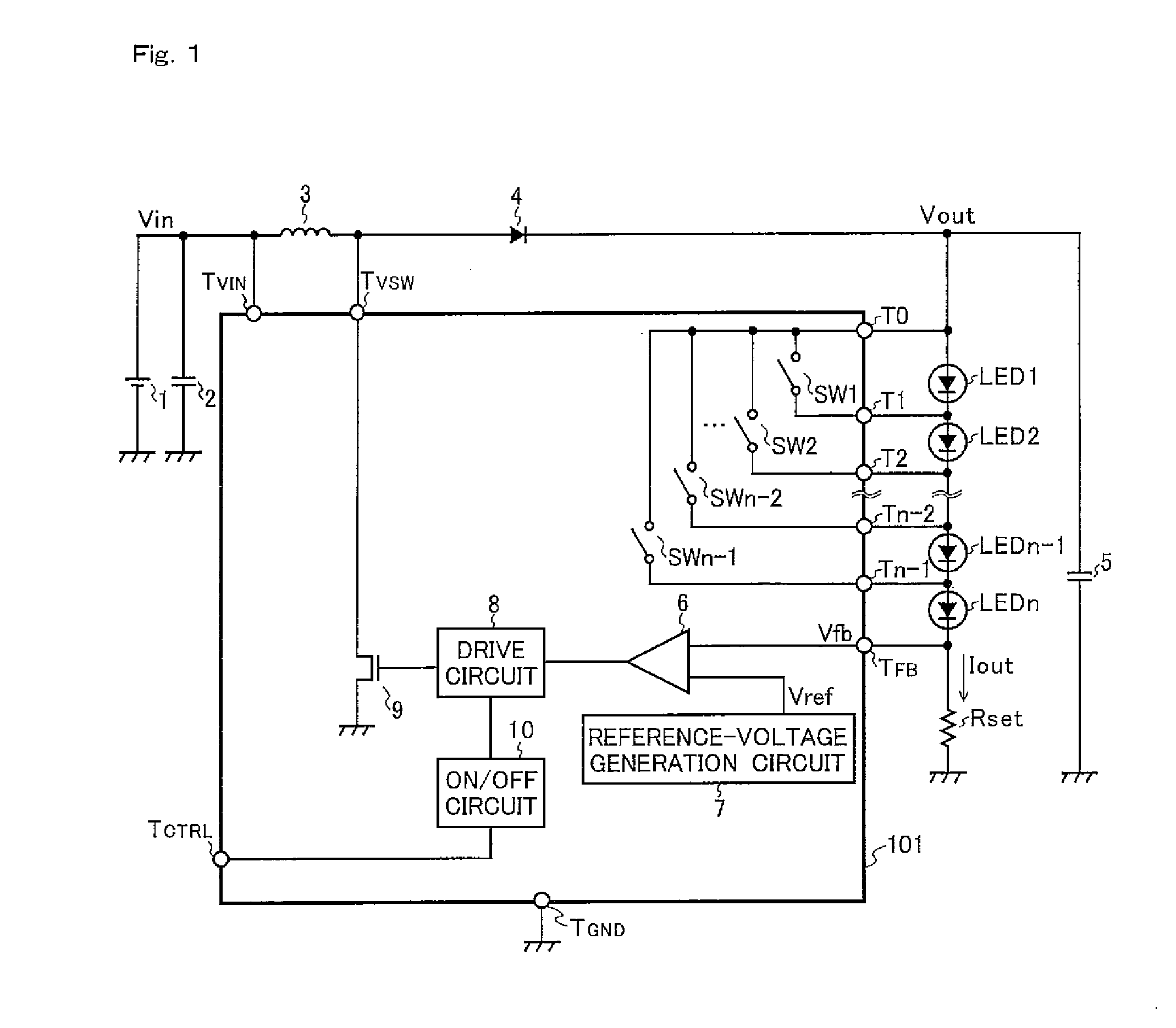
[0057]The lit-LED-number-control-switch control circuit 11″ controls the turning on and off of the lit-LED-number control switches (here, the transistors TR1 to TRn−1) according to the signal received through the terminal TSEN. In this embodiment, since the signal received through the terminal TSEN is outputted from an illumination sensor 13, the lit-LED-number-control-switch control circuit 11″ controls the turning on and off of the lit-LED number control switches (here, the transistors TR1 to TRn−1) according to the signal outputted from the illumination sensor 13. For example, as the intensity of illumination detected by the illumination sensor 13 decreases, the lit-LED-number-control-switch control circuit 11″ increases the number of light-emitting diodes lit among the light-emitting diodes LED1 to LEDn. Thus, with the light-emitting-diode drive circuit shown in FIG. 6 according to the invention, it is possible to control light according to the intensity of ambient light.

[0058]A...

eighth embodiment

[0060]An eighth embodiment of the present invention will now be described. The configuration of a light-emitting-diode drive circuit according to the invention is the same as that (see FIG. 1) of the light-emitting-diode drive circuit according to the first embodiment of the invention.

[0061]According to the method in which a chopper regulator or the like is used as a drive circuit and light-emitting diodes are connected in series so that the same amount of forward current is passed when the light-emitting diodes are driven, when any one or more of the n light-emitting diodes connected in series with the output terminal of the drive circuit become defective and thus open-circuited, all the light-emitting diodes are usually turned off.

[0062]In contrast, in the light-emitting-diode drive circuit according to the eighth embodiment of the invention, even when any one or more of the light-emitting diodes LED1 to LEDn−1 become defective and thus open-circuited, one of the lit-LED-number co...


PUM


Abstract

A light-emitting-diode drive circuit for driving n (where n is a natural number equal to or greater than two) light-emitting diodes (LED1 to LEDn) connected in series includes n′ (where n′ is any natural number equal to or greater than two but equal to or less than n; here, n′=n−1) lit-LED number control switches (SW1 to SWn−1). Here, there are n′ ways of turning on only one of the n′ lit-LED number control switches (SW1 to SWn−1) and there are, as corresponding to those n′ ways, n′ ways of lighting different numbers of light-emitting diodes among the n light-emitting diodes (LED1 to LEDn) connected in series.

Description

[0001]This nonprovisional application claims priority under 35 U.S.C. §119 (a) on Patent Application No. 2007-162447 filed in Japan on Jun. 20, 2007, the entire contents of which are hereby incorporated by reference.BACKGROUND OF THE INVENTION[0002]1Field of the Invention[0003]The present invention relates to a light-emitting-diode drive circuit and more particularly to a light-emitting-diode drive circuit having light-control capability.[0004]2. Description of Related Art[0005]In a light-emitting-diode drive circuit to which a plurality of light-emitting diodes are connected, to keep constant the amount of light emitted by each of the light-emitting diodes when they are lit, it is necessary to keep constant the forward current through the light-emitting diodes when they are driven. One method to pass the same amount of forward current through the light-emitting diodes when they are driven is to connect the light-emitting diodes in series using a chopper regulator or the like as a d...

Claims


Application Information

Patent Timeline
Patent Type & Authority Applications(United States)
IPC IPC(8): H05B41/36H05B37/02H01L33/00
CPCH05B33/0815H05B33/083H05B33/0842H05B33/0851H05B33/089Y02B20/346H05B45/48Y02B20/30H05B45/54H05B45/38
Inventor TATSUKAWA, MASAAKI
Owner SHARP KK
Why Eureka
Try Eureka