Method and device for long-range torsional guided-wave inspection of piping with a partial excitation and detection around the pipe circumference

Active Publication Date: 2008-12-25
SOUTHWEST RES INST
View PDF15 Cites 21 Cited by
  • Summary
  • Abstract
  • Description
  • Claims
  • Application Information

AI Technical Summary

Benefits of technology

[0022](2) A curved MsS probe is then placed over the thin magnetostrictive strip in position on the pipe surface. The plate MsS probe is either a core type (such as disclosed in U.S. Pat. No. 6,294,912 referenced above) or a flat coil type (such as disclosed in U.S. Pat. No. 6,396,262 also referenced above). A frame and attachment belt may be provided to secure the MsS probe to the pipe. The band or belt is tensioned sufficiently to keep the frame against the pipe and the magnetostrictive strip pressed against the pipe. This is further facilitated by the use of an elastic or air-operated bladder to achieve close contact and good mechanical coupling between the magnetostrictive strip and the plate MsS probe assembly, and to evenly distribute the pressure on the strip.

Problems solved by technology

(1) First, a thin magnetostrictive strip (preferred material is the iron cobalt alloy disclosed in U.S. Pat. No. 6,917,196 referenced above) is positioned on the pipe under inspection along the pipe circumference. To minimize the generation of unwanted extraneous signals, the length of the strip is preferably about four times the T (torsional wave) wavelength at the operating frequency or approximately equal to one-half of the pipe circumference, whichever is shorter. When the length of the strip is less than the above, the quality of data will be degraded due to the generation of unwanted signals. That is, the shorter the strip length, the greater the degradation. The width of the strip should be the same as, or slightly larger than, the width of the plate MsS probe being used (described in detail below). The magnetostrictive strip can be attached to the pipe by bonding with an adhesive (such as epoxy), using double-sided adhesive tape, or by simply applying pressure to the strip for mechanical coupling. The strip is magnetized along the lengthwise direction for T-wave MsS operation (as disclosed in U.S. Pat. No. 6,429,650 referenced above).
(2) A curved MsS probe is then placed over the thin magnetostrictive strip in position on the pipe surface. The plate MsS probe is either a core type (such as disclosed in U.S. Pat. No. 6,294,912 referenced above) or a flat coil type (such as disclosed in U.S. Pat. No. 6,396,262 also referenced above). A frame and attachment belt may be provided to secure the MsS probe to the pipe. The band or belt is tensioned sufficiently to keep the frame against the pipe and the magnetostrictive strip pressed against the pipe. This is further facilitated by the use of an elastic or air-operated bladder to achieve close contact and good mechanical coupling between the magnetostrictive strip and the plate MsS probe assembly, and to evenly distribute the pressure on the strip.

Method used


Image

  • Method and device for long-range torsional guided-wave inspection of piping with a partial excitation and detection around the pipe circumference
  • Method and device for long-range torsional guided-wave inspection of piping with a partial excitation and detection around the pipe circumference
  • Method and device for long-range torsional guided-wave inspection of piping with a partial excitation and detection around the pipe circumference

Examples


Embodiment Construction

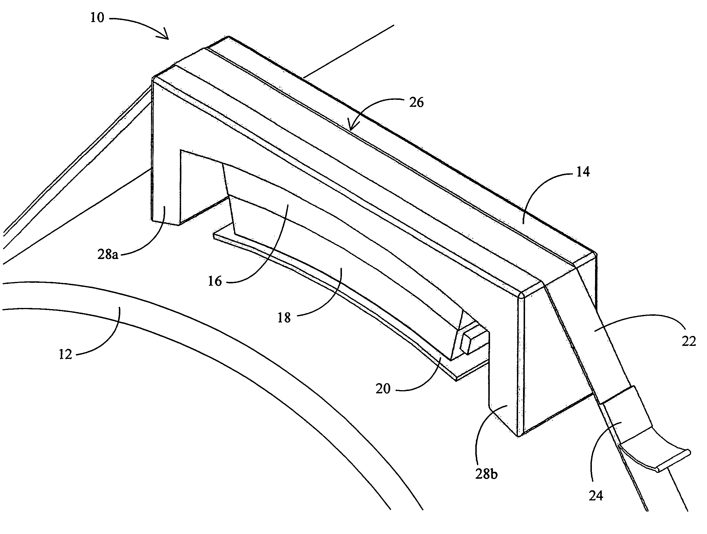
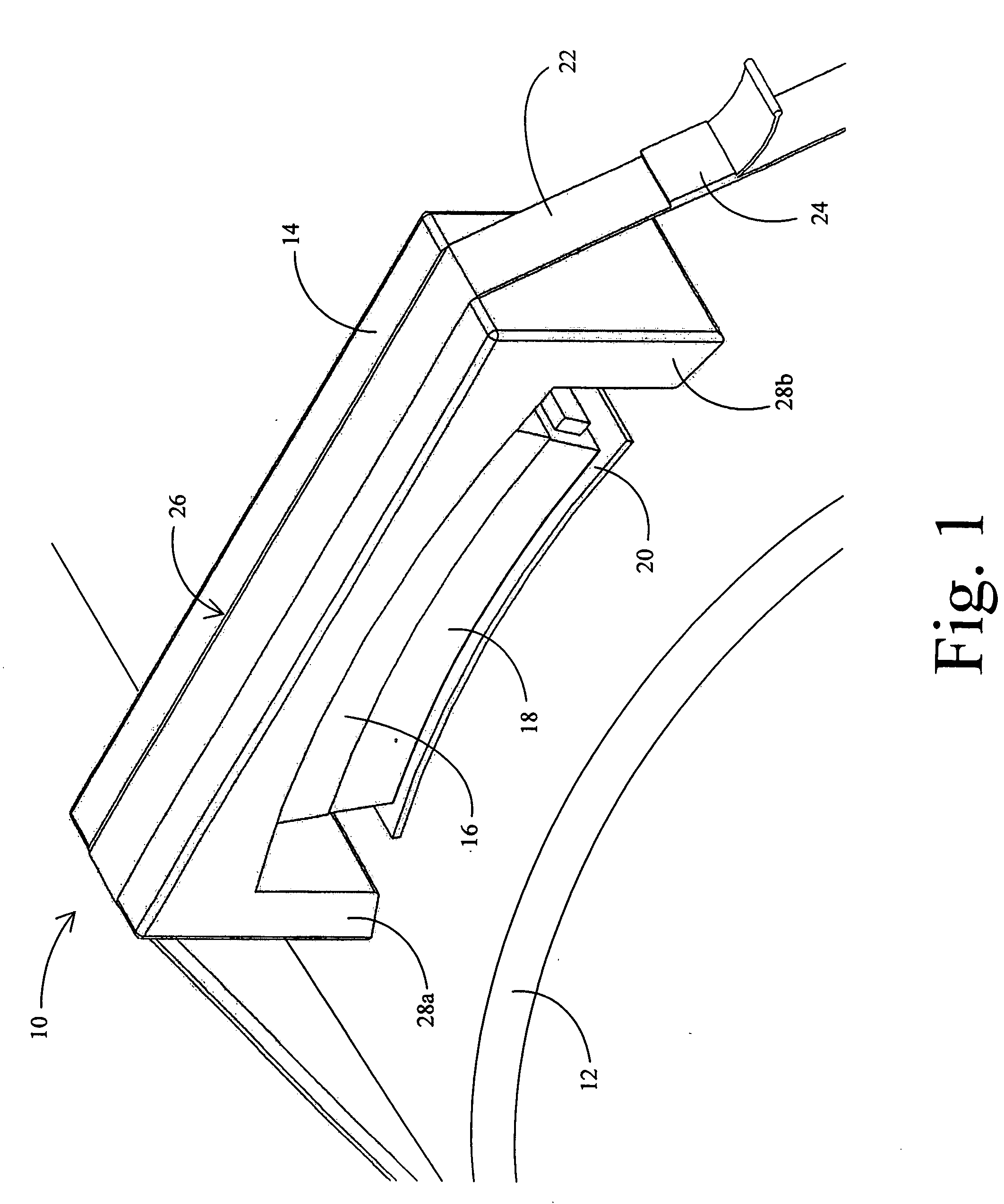
[0030]Reference is made first to FIG. 1 for a brief description of the overall plate magnetostrictive sensor (MsS) assembly of the present invention positioned as it would normally be placed in conjunction with the external curved surface of a cylindrical pipe or tube. Plate magnetostrictive sensor (MsS) assembly 10 is positioned on the external surface of pipe 12 and encompasses a radial portion of the entire circumference of the pipe. Assembly 10 is primarily comprised of a inverted U-shaped frame 14 held in place by belt 22 that encircles the pipe 12. Belt 22 is tensioned by buckle tensioning device 24 in a manner that secures the sensor assembly firmly against the external surface of the pipe. Belt 22 is maintained on frame 14 within belt slot 26 which is a channel depression that prevents belt 22 from slipping off of frame 14 while under tension or while the sensor assembly is being positioned into place.

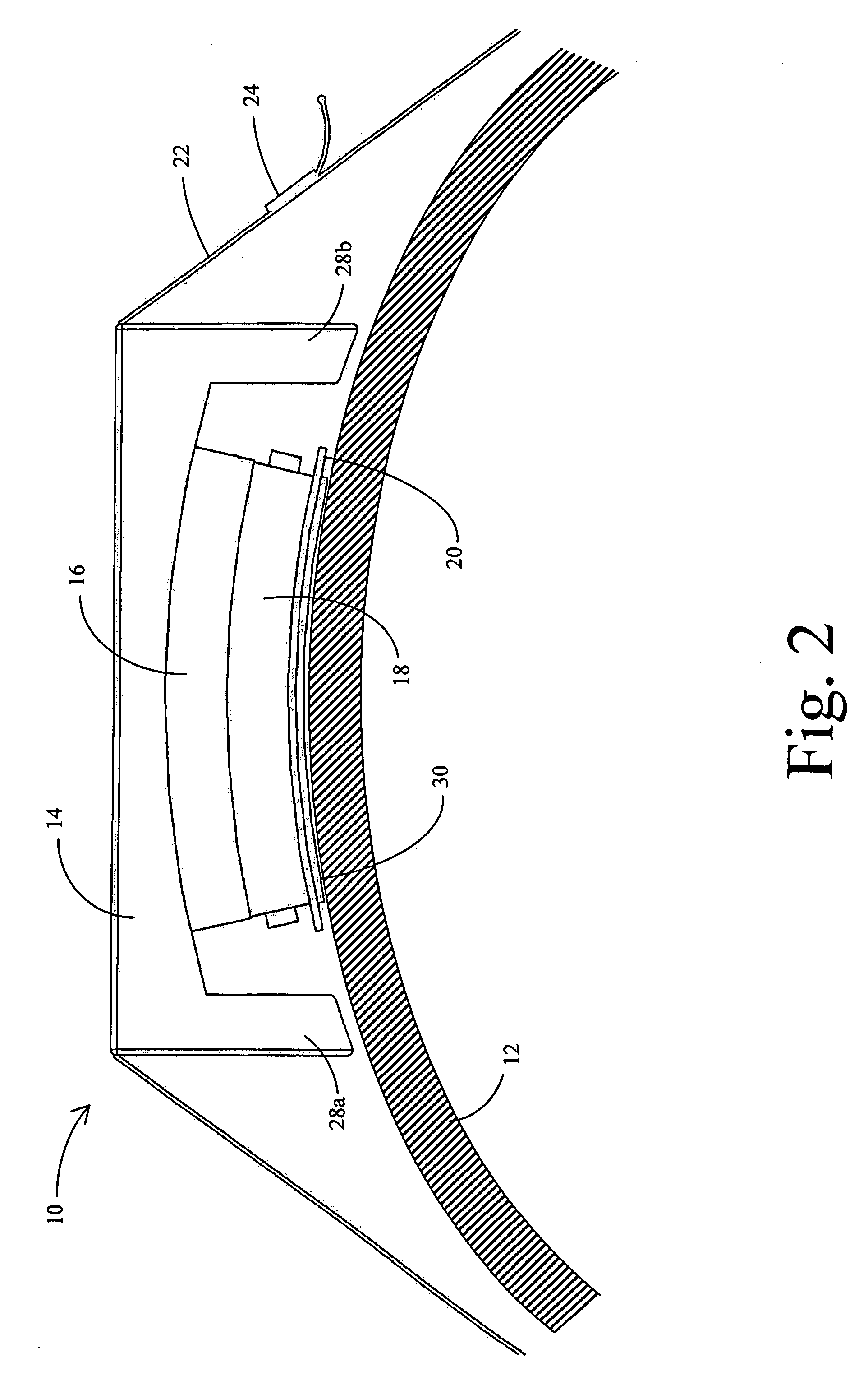
[0031]A plate magnetostrictive sensor probe 18 is positioned on top of pad...


PUM


Abstract

Sensor assemblies and methods are described that facilitate the use of a long-range torsional guided-wave inspection system for inspecting pipes, tubes, or other longitudinal cylindrical structures, with a partial excitation and detection around the pipe circumference. The sensor assemblies comprise a plate-type magnetostrictive sensor probe positioned beneath a compressible / expandable bladder and an inverted U-shaped frame that retain and position the sensor probe against the external wall of the pipe under inspection. Preferably, a magnetostrictive strip is positioned in direct contact with the pipe wall over which the plate magnetostrictive sensor probe is positioned. The probe is preferably curved to match the curvature of the external surface of the pipe. A pad may be positioned between the probe and the magnetostrictive strip to improve compliance with irregular pipe surfaces. The frame (and therefore the sensor assembly) is held in place by a belt that encircles the pipe and may be tensioned in order to pull the frame against the pipe, and through the compressive force associated with the bladder, direct the magnetostrictive sensor probe against the surface of the pipe or against the magnetostrictive strip positioned on the surface of the pipe. Methods are described for placement of the magnetostrictive strip and the positioning of the magnetostrictive sensor probe.

Description

BACKGROUND OF THE INVENTION[0001]1. Field of the Invention[0002]The present invention relates generally to methods and systems for non-destructive testing and inspection of pipes, tubes, and other longitudinal cylindrical structures. The present invention relates more specifically to methods and systems for accurately positioning long-range torsional guided-wave inspection sensors on pipes, tubes, and other cylindrical structures to create partial excitation and detection around the pipe circumference.[0003]2. Description of the Related Art[0004]Long-range, guided-wave inspection technology is an emerging technology that has the capability of quickly surveying a large volume of a structure for defects and providing comprehensive condition information on the integrity of the structure. Using relatively low-frequency (typically under 100 kHz) guided-waves in the pulse-echo testing mode, this technology performs a 100% volumetric examination of a large area of a structure and detects a...

Claims


Application Information

Patent Timeline
IPC IPC(8): G01N27/82
CPCG01N27/82G01N29/223G01N29/2412G01N2291/0425G01N2291/044G01N2291/2634
Inventor KWUN, HEGEONMATSUMOTO, HIROTOSHICRANE, JAMES F.
Owner SOUTHWEST RES INST
Why Eureka
Try Eureka