
Touch Sensor and Method for Operating a Touch Sensor

a technology of touch sensor and touch sensor, which is applied in the direction of instruments, computing, electric digital data processing, etc., can solve the problems of not being conductive, not using capacitive touch panels, and not being able to input information

Inactive Publication Date: 2008-12-25
NOKIA CORP
View PDF6 Cites 83 Cited by
  • Summary
  • Abstract
  • Description
  • Claims
  • Application Information

AI Technical Summary

Benefits of technology

[0010]To provide for an easy-to-use, multi-purpose input device, the application provides for an apparatus with a first conductive layer with first and second electrodes, a second conductive layer with third electrodes, a spacer spatially spacing the first conductive layer from the second conductive layer, the first electrode being arranged at least for capacitive touch detection, and the second and third electrodes being arranged for resistive touch detection.
[0011]It has been found that combining capacitive and resistive touch detection increases the use cases of touch sensors. Resistive touch detection provides for support of a pen use, gives a good resolution for the detected point of contact and provides for force recognition. For example, the point of contact can be located with a high spatial resolution. Further, the force by which the first and second conductive layers are pressed together can be approximated. Capacitive touch sensing provides for sensing multi-touch. Further, it is not necessary to come into physical contact with the first conductive layer, as proximity detection is possible. Proximity detection allows for sensing conductive pieces, such as fingers, in the spatial proximity of the first conductive layer, as already the spatial proximity causes a capacitive sensor sensing a change in the electrical potential. Further, as capacitive touch detection requires only little or even no force applied on the first conductive layer, it is possible to “swipe” scroll bars or the like on a user interface with a simple movement of a finger or a hand of a user.
[0012]Providing only a first and a second conductive layer provides for the advantage of reduced thickness, cost and complexity compared to known touch sensors. Providing the second electrodes on the first conductive layer and the third electrodes on the second conductive layer may allow for resistive touch sensing with only five wires for connecting the second and third electrodes. When the first conductive layer is pressed onto the second conductive layer, a voltage gradient may be measured by the second electrodes on the first conductive layer. The voltage may already be applied by the third electrodes on the second conductive layer and transferred, upon pressing the layers together, to the first conductive layer and further sensed by the second electrodes.

Problems solved by technology

Using capacitive type touch panels is limited to input devices, which are conductive.
Stylus pens, which are not conductive, do not allow inputting information into a capacitive type touch panel.
Thus, the conductive layers may have a low resistance.

Method used


Image

  • Touch Sensor and Method for Operating a Touch Sensor
  • Touch Sensor and Method for Operating a Touch Sensor
  • Touch Sensor and Method for Operating a Touch Sensor

Examples


Embodiment Construction

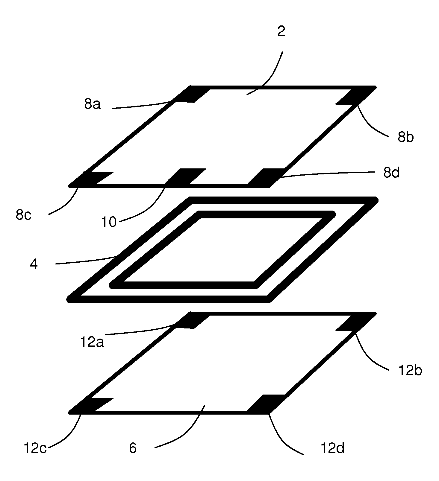
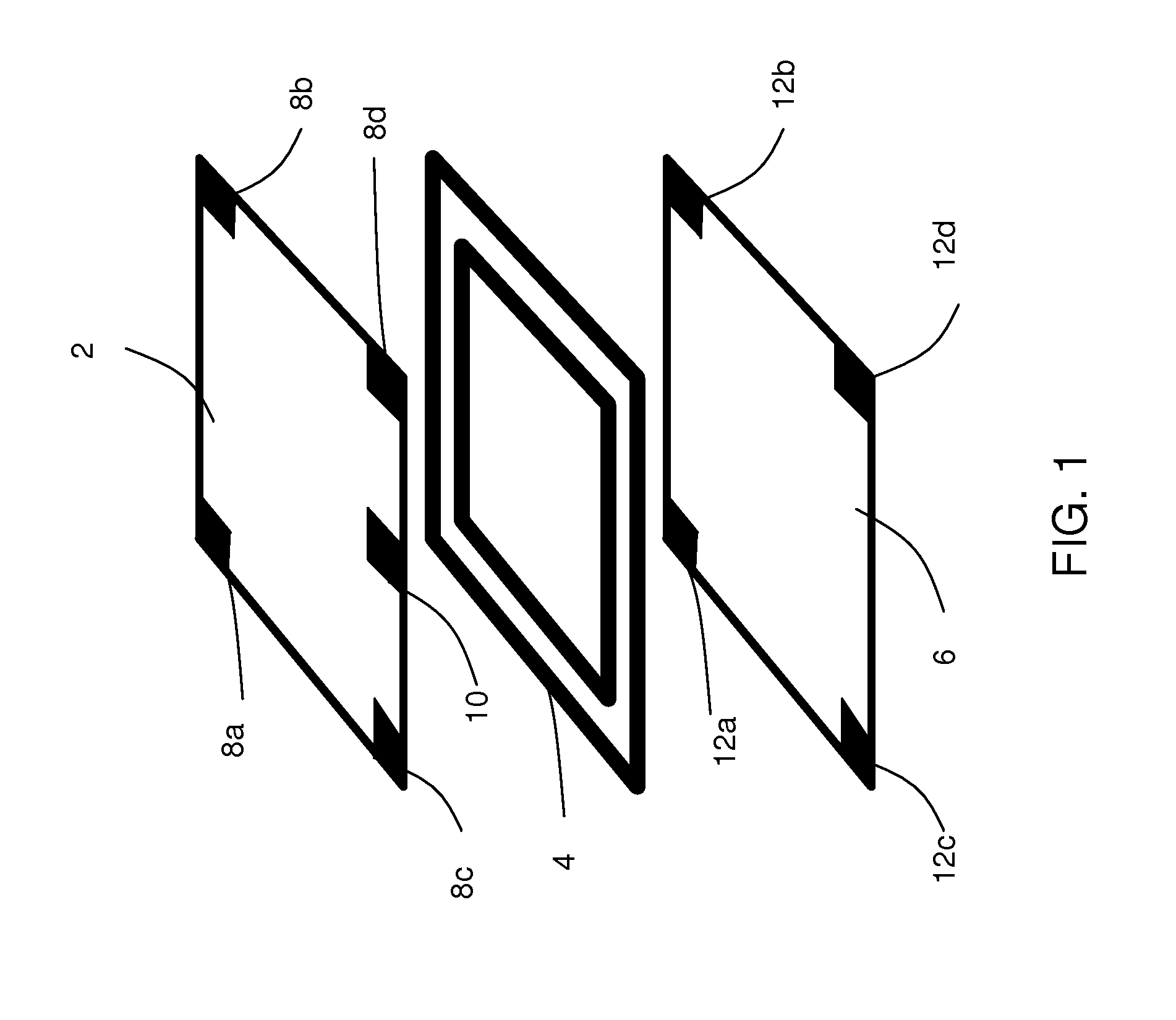
[0059]FIG. 1 illustrates a first conductive layer 2, a spacer 4, and a second conductive layer 6. The first conductive layer 2 may be made of a flexible material. The first conductive layer 2 may be made of Indium-Tin-Oxide. The first conductive layer 2 may be arranged as a flexible matrix. The second conductive layer 6 may be made of a stable material. The second conductive layer 6 may be made of Indium-Tin-Oxide. The second conductive layer 6 may be arranged on a stable substrate or within a stable matrix. The spacer 4 may be made of an insulating material. The first conductive layer 2 may be positioned above spacer 4 and spacer 4 may be positioned above second conductive layer 6. The illustration is an exploded view of an apparatus according to embodiments.

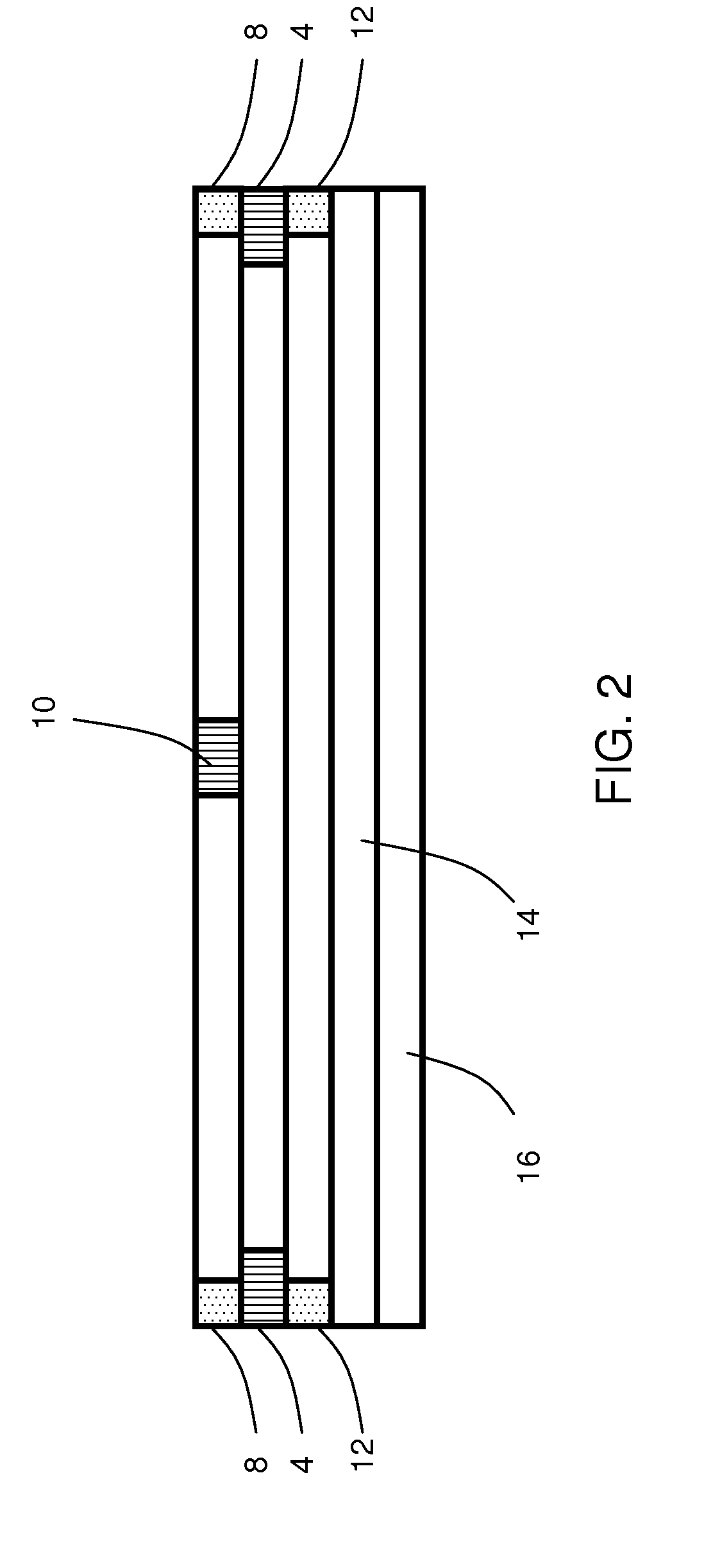
[0060]For operating the touch sensor, the first conductive layer 2, the spacer 4, and the second conductive layer 6 are stacked on top of each other building a monolithic structure.

[0061]First conductive layer 2 has on its corn...


PUM


Abstract

Touch detection within display devices with a first conductive layer with first and second electrodes, a second conductive layer with third electrodes, a spacer spatially spacing the first conductive layer from the second conductive layer, the first electrodes being arranged for capacitive touch detection, and the second and third electrodes being arranged for resistive touch detection.

Description

BACKGROUND OF THE INVENTION[0001]1. Technical Field[0002]The present application relates to an apparatus for touch detection, a touch sensor, a touch sensitive display, a multimedia device with a touch sensor as well as a method for operating such an apparatus.[0003]2. Discussion of Related Art[0004]Personal computers and multimedia devices as well as communication devices provide for a user interface (UI) for interacting with a user. The user interface allows the user for operating the device according to his needs. In order to operate the device via the user interface, input means need to be provided. Through these input means, users can input information such as simple operation instructions as well as letter and digits.[0005]One kind of input devices known in the art are touch panels, which are known to be simple, easy to carry, reliable, and capable of inputting simple operating instructions as well as letters and digits. Different kinds of touch panels are known, for example r...

Claims


Application Information

Patent Timeline
Patent Type & Authority Applications(United States)
IPC IPC(8): G06F3/041
CPCG06F3/044G06F3/045G06F3/0445G06F2203/04103G06F2203/04106
Inventor ANTILA, MIKARAMO, TEEMUKARHINIEMI, MARKO
Owner NOKIA CORP
Learn More