
Flexible wiring member, liquid droplet jetting head, and method for connecting flexible wiring member and device

a flexible wiring and wire technology, applied in printed circuit manufacturing, printed circuit aspects, printing, etc., can solve the problems of high cost of flexible wires of double-sided wiring types as compared to single-sided wiring types, and achieve the effect of simplifying the process and facilitating the connection of wires

Active Publication Date: 2008-12-25
BROTHER KOGYO KK
View PDF3 Cites 29 Cited by
  • Summary
  • Abstract
  • Description
  • Claims
  • Application Information

AI Technical Summary

Benefits of technology

[0009]The present invention has been made to solve the abovementioned problems, and an object of the present invention is to realize a high densification of wires in a flexible wiring member while suppressing a rise in the cost.
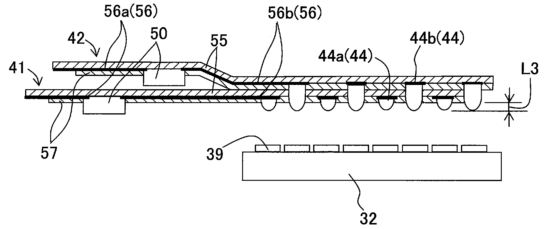
[0045]In the method of the present invention, after the first flexible wiring member and the second flexible wiring member may be positioned and stacked with each other, the through holes are formed in the first flexible wiring member, and the electrodes of the second flexible wiring member are formed. In this case, it is possible to expose the electrode of the second flexible wiring from the through hole by removing a part of the covering material or the substrate of the second flexible wiring simultaneously with forming the through hole in the first flexible wiring. Therefore, it is possible to simplify the process, and connections of the wires become easy.

Problems solved by technology

Such a flexible wire of a double-sided wiring type has a high cost as compared to a single-sided wiring type in which the wiring is made on only one surface.

Method used


Image

  • Flexible wiring member, liquid droplet jetting head, and method for connecting flexible wiring member and device
  • Flexible wiring member, liquid droplet jetting head, and method for connecting flexible wiring member and device
  • Flexible wiring member, liquid droplet jetting head, and method for connecting flexible wiring member and device

Examples


Embodiment Construction

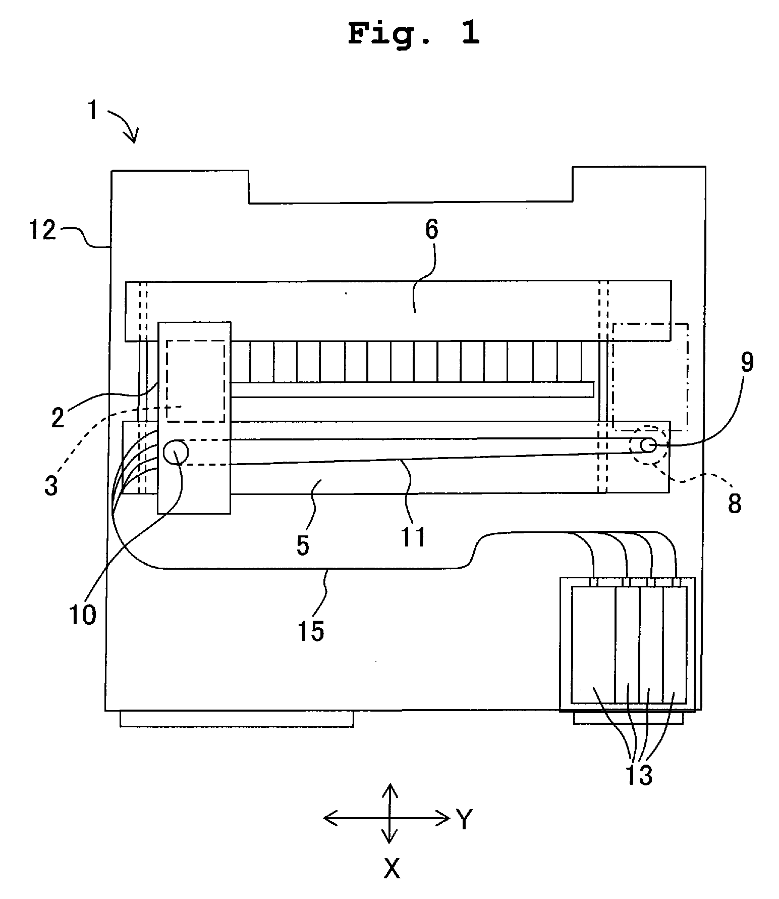
[0059]A first embodiment of the present invention will be described below with reference to the accompanying diagrams. FIG. 1 is a schematic plan view of an ink-jet printer (recording apparatus) 1 according to (as an embodiment of) a liquid jetting apparatus of the present invention. The ink-jet printer 1 jets an ink from nozzles. The ink-jet printer 1 may be applied to an independent printer apparatus. Or the ink-jet printer 1 may be applied to a printer mechanism (recording section) of a multi-function apparatus which is provided with a plurality of functions such as a facsimile function and a copy function. In the following description, a direction of jetting of the ink from the nozzles to a medium is defined as a downward direction and a direction opposite to the downward direction is defined as an upward direction.

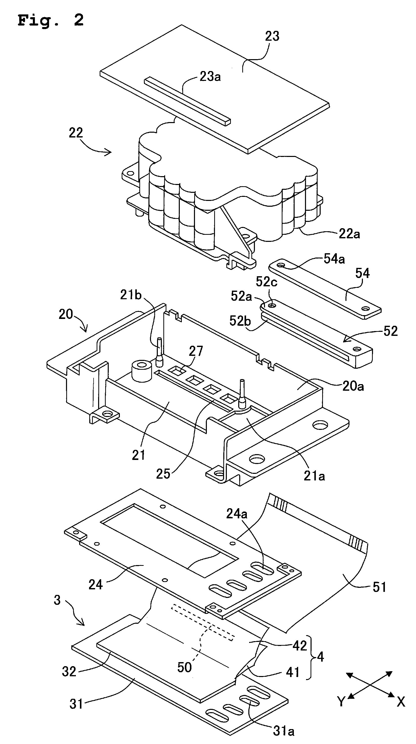
[0060]As shown in FIG. 1, the recording apparatus (ink-jet printer) 1 includes a carriage 2. A jetting head (liquid jetting apparatus) 3 is mounted on the carriage 2....


PUM

PropertyMeasurementUnit
Thicknessaaaaaaaaaa
Flexibilityaaaaaaaaaa
Areaaaaaaaaaaa

Abstract

A flexible wiring member which connects a device and an external signal source has a plurality of wire members in which a plurality of wires are formed on one surface of a substrate, and a plurality of wire members is stacked to face the device. A plurality of bumps for connecting with the device are provided to the wires on a surface, of the wirings, facing the device. Bumps of one of the wire members overlapping with the other of the wire members face the device via the through hole formed in the other of the wire members. Accordingly, it is possible to realize high densification of wires in the flexible wiring while suppressing a rise in a cost.

Description

CROSS REFERENCE TO RELATED APPLICATION[0001]The present application claims priority from Japanese Patent Application No. 2007-161119, filed on Jun. 19, 2007, the disclosure of which is incorporated herein by reference in its entirety.BACKGROUND OF THE INVENTION[0002]1. Field of the Invention[0003]The present invention relates to a flexible wiring member which connects a device and an external signal source, a liquid droplet jetting apparatus in which the flexible wiring member is used, and a method of connecting the flexible wiring member and the device.[0004]2. Description of the Related Art[0005]In a liquid droplet jetting apparatus which jets liquid droplets from nozzles, a driving signal is input to an actuator having drive portions each corresponding to one of the nozzles, via a flexible wire. Accordingly, the drive signal selectively applies a jetting pressure to a liquid.[0006]In the liquid droplet jetting apparatus, when the number of nozzles is increased and the nozzles are...

Claims


Application Information

Patent Timeline
IPC IPC(8): B41J2/145H05K1/02H05K3/36
CPCB41J2/14209B41J2/1609B41J2/1623B41J2/1632B41J2002/14217B41J2002/14225B41J2002/14306B41J2002/14419B41J2002/14459B41J2002/14491H05K1/147H05K3/363H05K2201/041H05K2201/09063H05K2203/063Y10T29/49126
Inventor KUBO, TOMOYUKIKONDO, HIROFUMI
Owner BROTHER KOGYO KK
Learn More