Projection type image display device

a projection type, image display technology, applied in the direction of picture reproducers, television systems, instruments, etc., can solve the problems of uneven display of projected images, increase of spot scanned regions, and suppressed speck in projected images, etc., to achieve suppressed uneven lines in the gap region, the effect of suppressing speck in the projected imag

Inactive Publication Date: 2008-12-25
SANYO ELECTRIC CO LTD +1
View PDF2 Cites 5 Cited by
  • Summary
  • Abstract
  • Description
  • Claims
  • Application Information

AI Technical Summary

Benefits of technology

[0014]According to the second aspect, since the spot size of the beam in the projected region is set to be smaller than the width of one pixel in the direction vertical to the scanning direction, the speckle in the projected image is suppressed. Furthermore, since the scanning position of each pixel is shifted in the direction vertical to the scanning direction in terms of time, the regions of the gap shown in FIGS. 6A and 6B are reduced. Therefore, the unevenness on display in the line-shape caused due to the region of the gap is suppressed.

Problems solved by technology

This type of laser projectors have a problem that speckle occurs to a projected image due to interference of the laser light.
However, when the diameter of the spot is reduced as mentioned above, a region that cannot be scanned by the spot increases in the projected region, and another problem eventually arises that unevenness on display occurs to the projected image.
As mentioned, when the diameter of the spot is made smaller than the width of one pixel, the speckle is suppressed while the unevenness on display occurs to the projected image, causing problems.

Method used


Image

  • Projection type image display device
  • Projection type image display device
  • Projection type image display device

Examples


Embodiment Construction

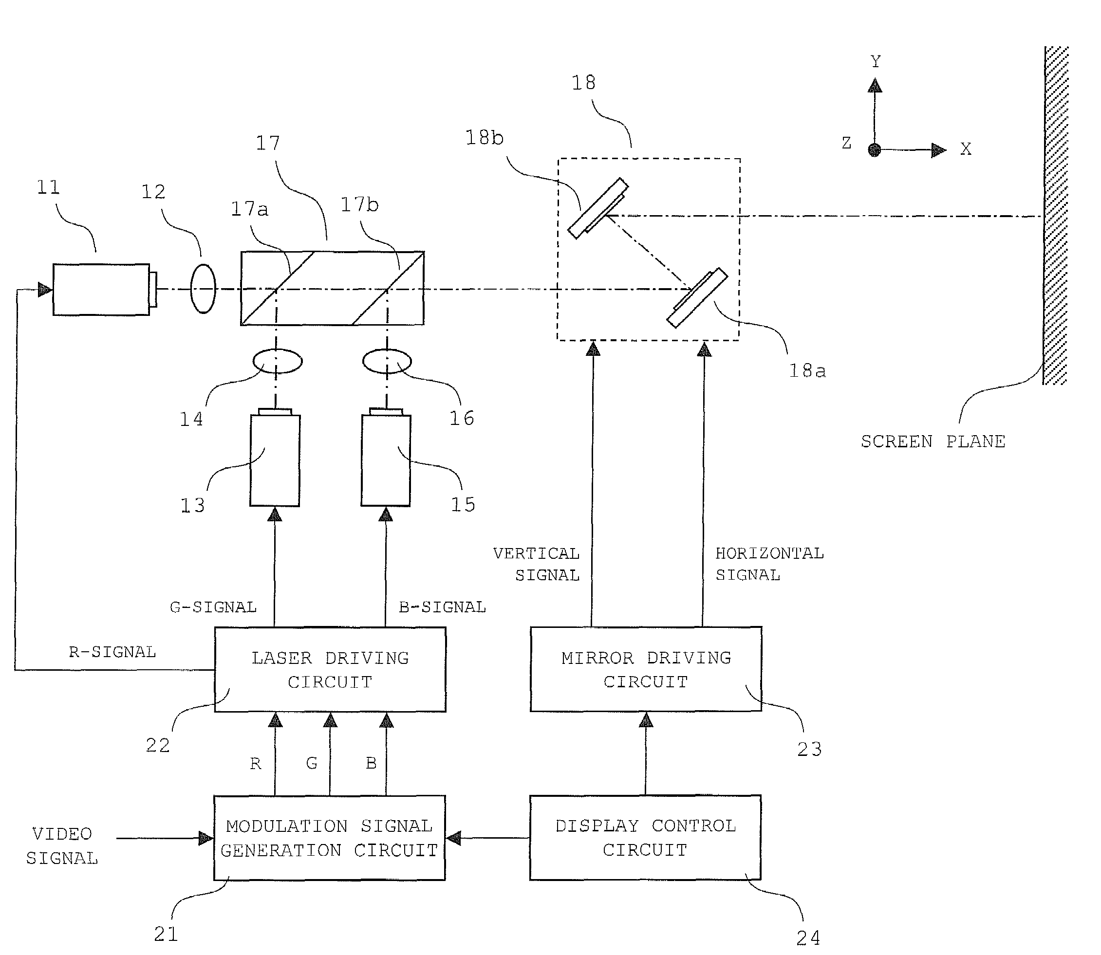
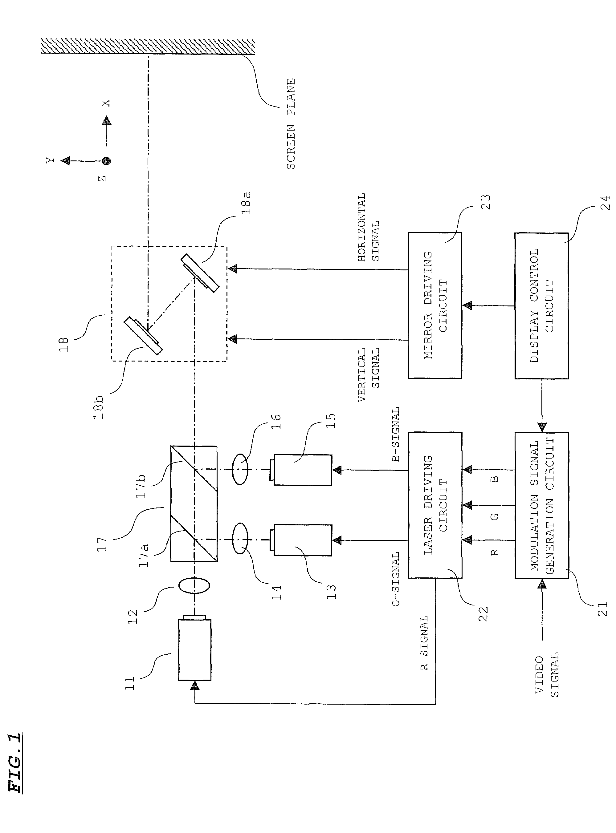
[0023]A configuration of the laser projector according to the embodiment is shown in FIG. 1.

[0024]In the drawing, reference number 11 denotes a laser light source for emitting laser light in a red wavelength band (hereinafter, referred to as “R-light”). Reference number 12 denotes an optical system for shaping the R-light emitted from the laser light source 11 to a beam spot with a predetermined diameter on the screen plane. Reference number 13 denotes a laser light source for emitting laser light in a green wavelength band (hereinafter, referred to as “G-light”). Reference number 14 denotes an optical system for shaping the G-light emitted from the laser light source 13 to a beam spot with a predetermined diameter on the screen plane. Reference number 15 denotes a laser light source for emitting laser light in a blue wavelength band (hereinafter, referred to as “B-light”). Reference number 16 denotes an optical system for shaping the B-light emitted from the laser light source 15 t...


PUM


Abstract

A beam modulated by a video signal scans a projected region. A spot size of the beam in the projected region is set to be smaller than a width of one pixel in a direction vertical to a scanning direction. A group of pixels disposed in the scanning direction is scanned by the beam a plurality of times to display one screen. A scanning position of the beam with regard to the group of the pixels is shifted in the direction vertical to the scanning direction for every scanning turn to display one screen.

Description

[0001]This application claims priority under 35 U.S.C. Section 119 of Japanese Patent Application No. 2007-114062 filed Apr. 24, 2007, entitled “PROJECTION TYPE IMAGE DISPLAY DEVICE”.BACKGROUND OF THE INVENTION[0002]1. Field of the Invention[0003]The present invention relates to a projection type image display device for displaying an image by causing a beam to scan on a projected plane, and is preferable particularly in use for a case where a laser light source serves as a light emitting source.[0004]2. Description of the Related Art[0005]Today, scanning type laser projectors for displaying an image by scanning a screen plane with laser light have been developed. This type of laser projectors have a problem that speckle occurs to a projected image due to interference of the laser light. Various methods have been investigated to resolve this problem.[0006]One known method for suppressing the speckle is to reduce a size of a diameter of a spot on the screen plane. In general, in the ...

Claims


Application Information

Patent Timeline
Patent Type & Authority Applications(United States)
IPC IPC(8): H04N9/31
CPCG02B26/101
Inventor HISHIDA, MITSUOKI
Owner SANYO ELECTRIC CO LTD
Why Eureka
Try Eureka