

Image forming apparatus, control method therefor, and operation apparatus of equipment
a technology of image forming apparatus and control method, which is applied in the direction of instruments, static indicating devices, electrographic processes, etc., can solve the problems of cumbersome operation and difficulty in sufficiently improving the install and achieve the effect of improving the degree of freedom of installation environment, the operability of the image forming apparatus and the equipmen
- Summary
- Abstract
- Description
- Claims
- Application Information
AI Technical Summary
Benefits of technology
Problems solved by technology
Method used
Image

Examples
first embodiment
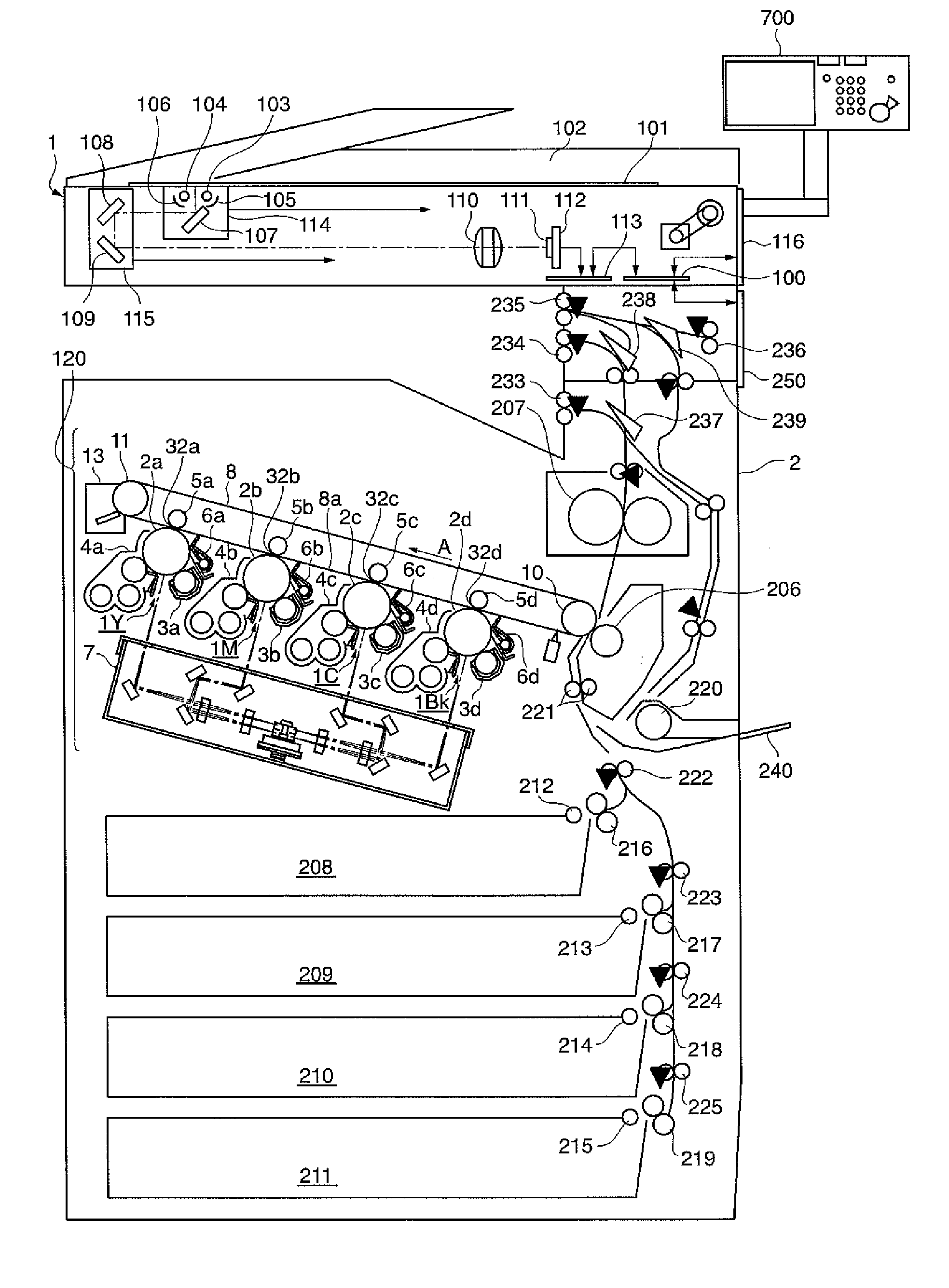
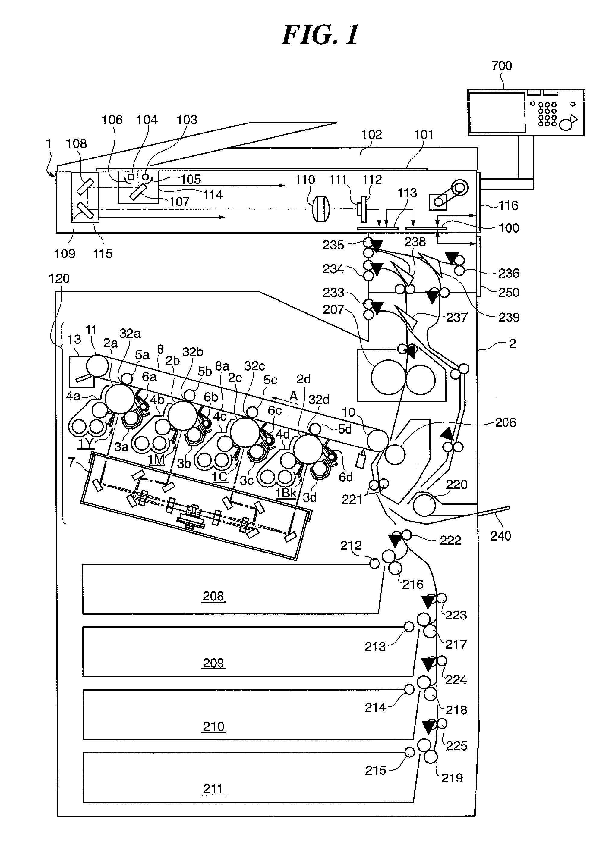
[0038]FIG. 1 is a vertical section view schematically showing the construction of an image forming apparatus according to a first embodiment of this invention. The image forming apparatus is a color image forming apparatus and comprised of a color reader unit 1 and a color printer unit 2.
[0039]First, the construction of the color reader unit 1 is described.
[0040]The color reader unit 1 includes an original tray glass (platen) 101 and an automatic document feeder (ADF) 102. Instead of the automatic document feeder 102, a mirror platen or a white platen (not shown) may be mounted.
[0041]The color reader unit 1 includes light sources 103, 104 for illuminating an original placed on the original tray glass 101. The light sources 103, 104 are each implemented by, for example, a halogen lamp, a fluorescent lamp, or a xenon tube lamp. Light from the light sources 103, 104 is converged by reflectors 105, 106 provided in the reader unit.
[0042]The color reader unit 1 includes mirrors 107 to 109...
second embodiment
[0124]An image forming apparatus according to a second embodiment of this invention is the same in construction as the image forming apparatus according to the above described first embodiment. Like parts which are the same or similar in construction to the first embodiment will be denoted by like reference numerals, and explanations thereof will be omitted. In the following, only points different from the first embodiment will be described.
[0125]In the second embodiment, a polygon motor in the laser exposure unit 7 is configured to be large in moment of inertia in order to rotatably drive the polygon mirror with stability. As a result, it takes time to start the polygon motor. Generally, a time period from 3 to 7 seconds is required to start the motor from a stopped state or rise the motor speed from low to high. When a heating source in the fixing unit 207 is in a cold state, it takes time to reach a temperature above which toner can be fixed to a recording sheet from the start of...
third embodiment
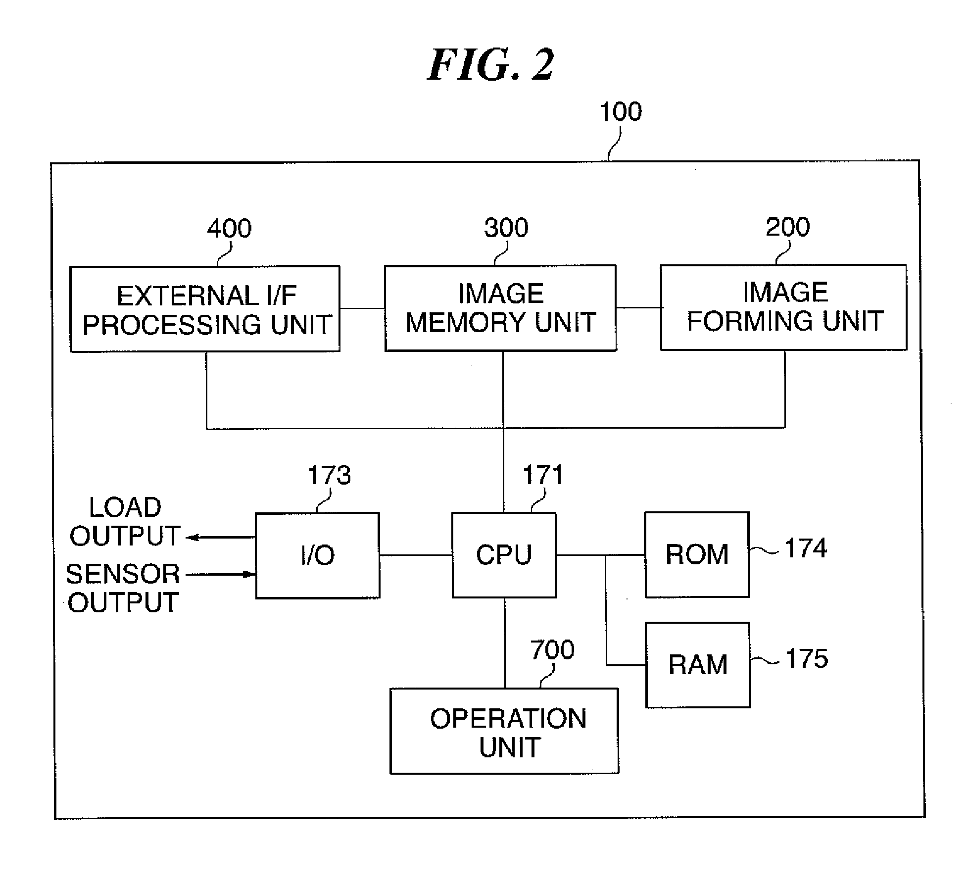
[0133]FIG. 13 schematically shows in flowchart a control process performed by an image forming apparatus according to a third embodiment of this invention. The control process is realized by the CPU 171 by reading out and executing a program stored in the ROM 174.
[0134]Referring to FIG. 13, the image forming apparatus is in a standby state in which the apparatus waits in a condition capable of performing the image formation. In the standby state, the protrusion 720a on the support member 720 is in a state detected by the sensor 710 or 711, i.e., the operation unit 700 is in a state facing the front or rear side of the image forming apparatus. In this state, whether or not the operation unit 700 is pivoted by an operator is determined, i.e., whether or not the protrusion 720a on the support member 720 is no longer detected by the sensors is determined. If it is determined in step S1000 that the protrusion 720a on the support member 720 becomes no longer detected by the sensors, the C...
PUM
 Abstract
Description
Claims
Application Information