
Skew controlled leadframe for a contact module assembly

a contact module and leadframe technology, applied in the direction of electrical apparatus casings/cabinets/drawers, coupling device connections, casings/cabinets/drawers details, etc., can solve the problem of increasing the difficulty and/or cost of manufacturing connectors, different lengths of terminals between corresponding contacts, and the difference in the time that a pair of identical signals takes. to achieve the effect of reducing skew

Active Publication Date: 2008-12-25
TYCO ELECTRONICS LOGISTICS AG (CH)
View PDF13 Cites 42 Cited by
  • Summary
  • Abstract
  • Description
  • Claims
  • Application Information

AI Technical Summary

Benefits of technology

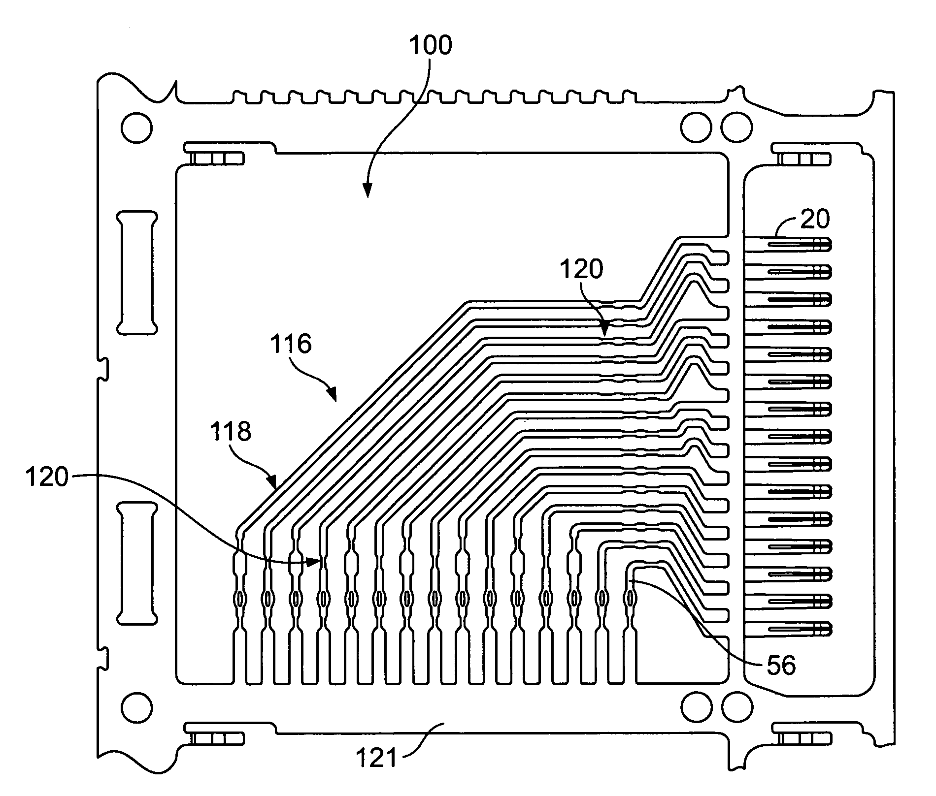
[0008]Optionally, the first terminal may have a first length between the ends, the second terminal may have a second length between the ends shorter than the first length, and the third terminal may have a third length between the ends shorter than the second length. Each of the terminals may have a transition section defined between a first plane extending perpendicularly through each of the terminals in the terminal set and a second plane extending perpendicularly through each of the terminals in the terminal set. The transition section of the first terminal may have a first transition length, the transition section of the second terminal may have a second transition length that is longer than the first transition length by a first amount, and the transition section of the third terminal may have a third transition length that is longer than the second transition length by a second amount that is the same as the first amount such that the skew between the first and second terminals is reduced by the same amount as the skew between the second and third terminals within the transition section. Optionally, the terminals may have predetermined lengths along the second transition portions that create predetermined amounts of skew between adjacent ones of the terminals, wherein the first transition portions each have different lengths such that the skew between the signal terminals is reduced by an amount when the leadframe is configured in the signal-signal-ground pattern and the skew between the signal terminals is reduced by the same amount when the leadframe is configured in the ground-signal-signal pattern. Optionally, the first transition portions of the first and second terminals may reduce the skew by the same amount as the first transition portions of the second and third terminals.

Problems solved by technology

However, different leadframes must be designed and manufactured for each of the contact modules having different terminal and / or contact patterns, which may increase the difficulty and / or cost of manufacturing the connector.
Another problem associated with known right angle contact modules is that the terminals have different lengths between the corresponding contacts.
Signal skew results from a difference in the time that a pair of identical signals takes to get from the mating edge to the mounting edge of the contact module.
However, due to the size of the contact assemblies, it is difficult and costly to exactly match the lengths of each of the terminals.
As such, skew remains a problem in many contact modules today.

Method used


Image

  • Skew controlled leadframe for a contact module assembly
  • Skew controlled leadframe for a contact module assembly
  • Skew controlled leadframe for a contact module assembly

Examples


Embodiment Construction

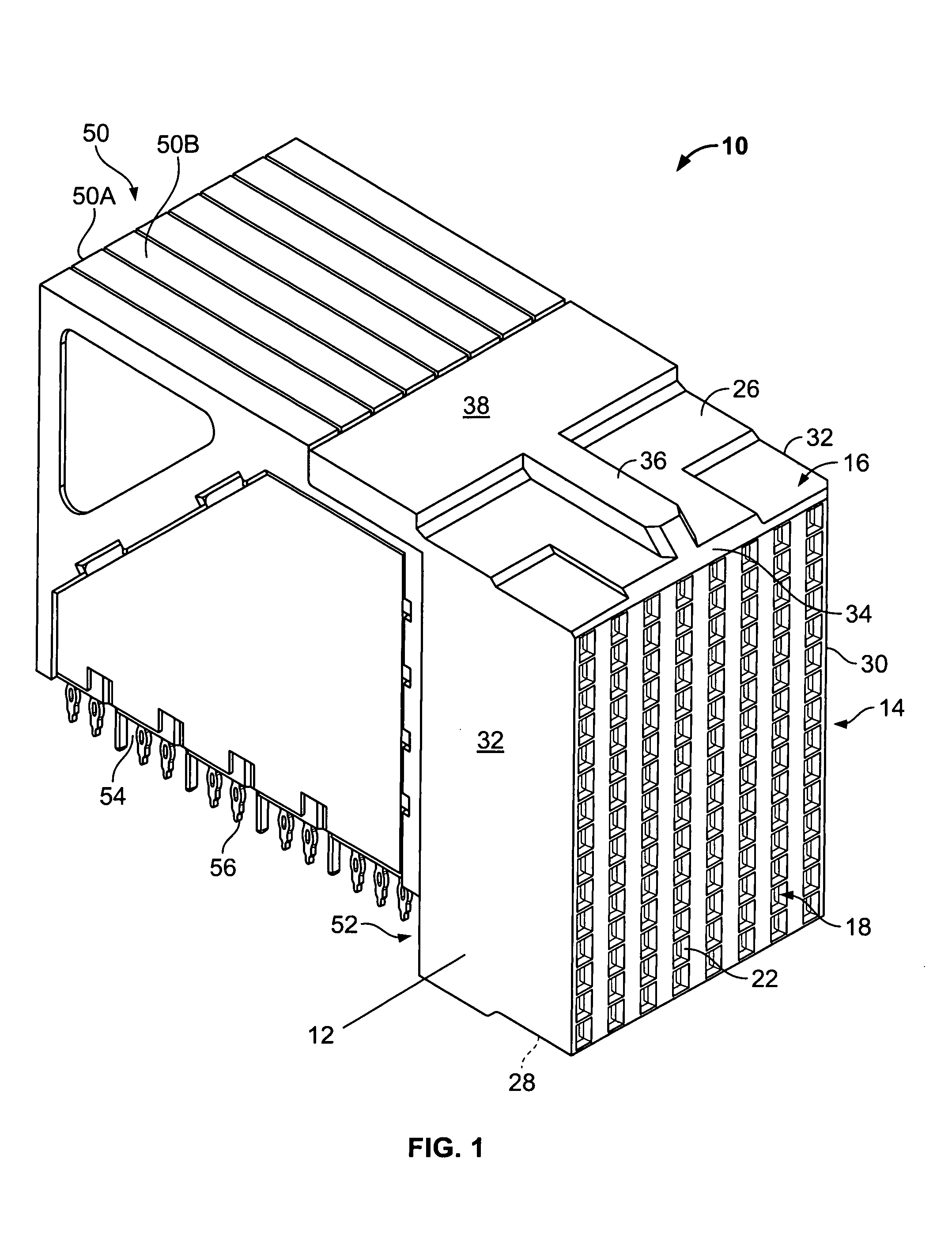
[0019]FIG. 1 illustrates an exemplary embodiment of an electrical connector 10. While the connector 10 will be described with particular reference to a receptacle connector, it is to be understood that the benefits herein described are also applicable to other connectors in alternative embodiments. The following description is therefore provided for purposes of illustration, rather than limitation, and is but one potential application of the inventive concepts herein.

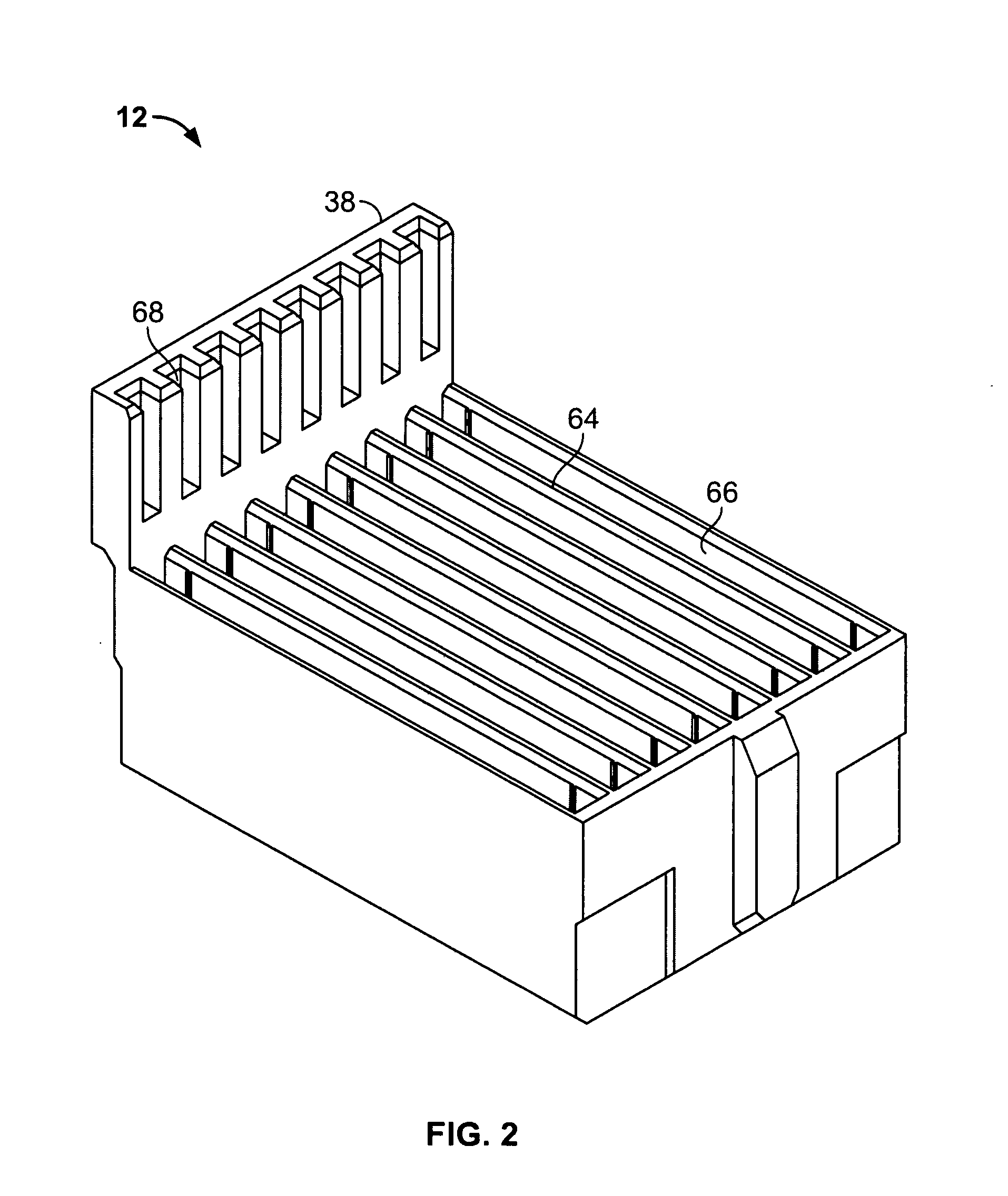
[0020]The connector 10 includes a dielectric housing 12 having a forward mating end 14 that includes a shroud 16 and a mating face 18. The mating face 18 includes a plurality of mating contacts 20 (shown in FIGS. 3 and 4), such as, for example, contacts within contact cavities 22, that are configured to receive corresponding mating contacts (not shown) from a mating connector (not shown). The shroud 16 includes an upper surface 26 and a lower surface 28 between opposed sides 30, 32. The upper and lower surfaces 26 and 2...


PUM


Abstract

A leadframe for a contact module assembly includes a terminal set having first, second and third terminals configured to operate in one of a signal-signal-ground pattern and a ground-signal-signal pattern. Each of the terminals have a length that extends between a mating end and a mounting end, wherein a difference in lengths between the first terminal and the second terminal is the same as a difference in lengths between the second terminal and the third terminal such that the terminal set has the same amount of skew between the terminals defining signal contacts in both the signal-signal-ground pattern and the ground-signal-signal pattern.

Description

BACKGROUND OF THE INVENTION[0001]This invention relates generally to contact module assemblies, and more particularly, to reduced skew leadframes for contact module assemblies.[0002]With the ongoing trend toward smaller, faster, and higher performance electrical components such as processors used in computers, routers, switches, etc., it has become increasingly important for the electrical interfaces along the electrical paths to also operate at higher frequencies and at higher densities with increased throughput.[0003]In a traditional approach for interconnecting circuit boards, one circuit board serves as a back plane and the other as a daughter board. The back plane typically has a connector, commonly referred to as a header, which includes a plurality of signal contacts which connect to conductive traces on the back plane. The daughter board connector, commonly referred to as a receptacle, also includes a plurality of contacts. Typically, the receptacle is a right angle connecto...

Claims


Application Information

Patent Timeline
Patent Type & Authority Applications(United States)
IPC IPC(8): H05K7/18
CPCH01R13/6587
Inventor ROTHERMEL, BRENT RYANSHARF, ALEX MICHAEL
Owner TYCO ELECTRONICS LOGISTICS AG (CH)
Learn More