X-ray imaging apparatus and x-ray imaging method

a technology of x-ray imaging and x-ray, applied in electrical equipment, medical science, diagnostics, etc., can solve the problems of exposing patients to radiation and requiring aborting scheduled procedures, and achieve the effect of inhibiting excessive x-ray radiation

Inactive Publication Date: 2008-12-25
CANON KK
View PDF6 Cites 28 Cited by
  • Summary
  • Abstract
  • Description
  • Claims
  • Application Information

AI Technical Summary

Benefits of technology

[0007]The present invention has been made in consideration of the above problems, and has as its object to provide an X-ray imaging technique that enab

Problems solved by technology

However, X-ray fluoroscopic examination and surgical support, while being extremely beneficial, unavoidably expose patients to radiation, and the exposure risk must always be taken in

Method used


Image

  • X-ray imaging apparatus and x-ray imaging method
  • X-ray imaging apparatus and x-ray imaging method
  • X-ray imaging apparatus and x-ray imaging method

Examples


first embodiment

Configuration of X-Ray Imaging Apparatus

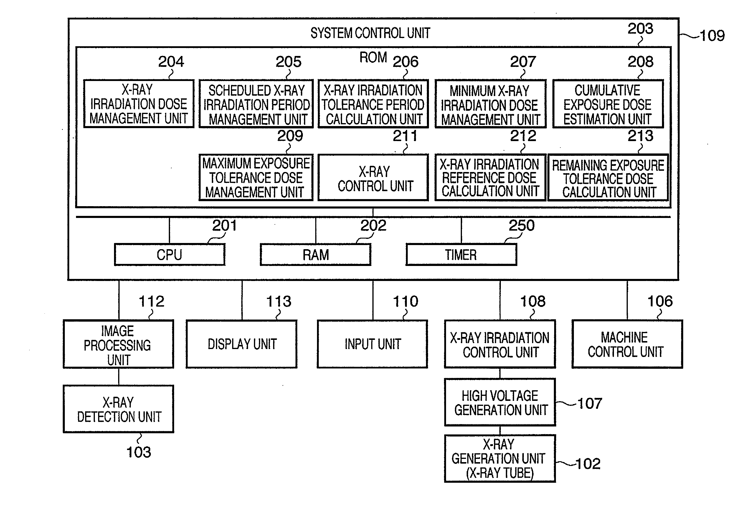
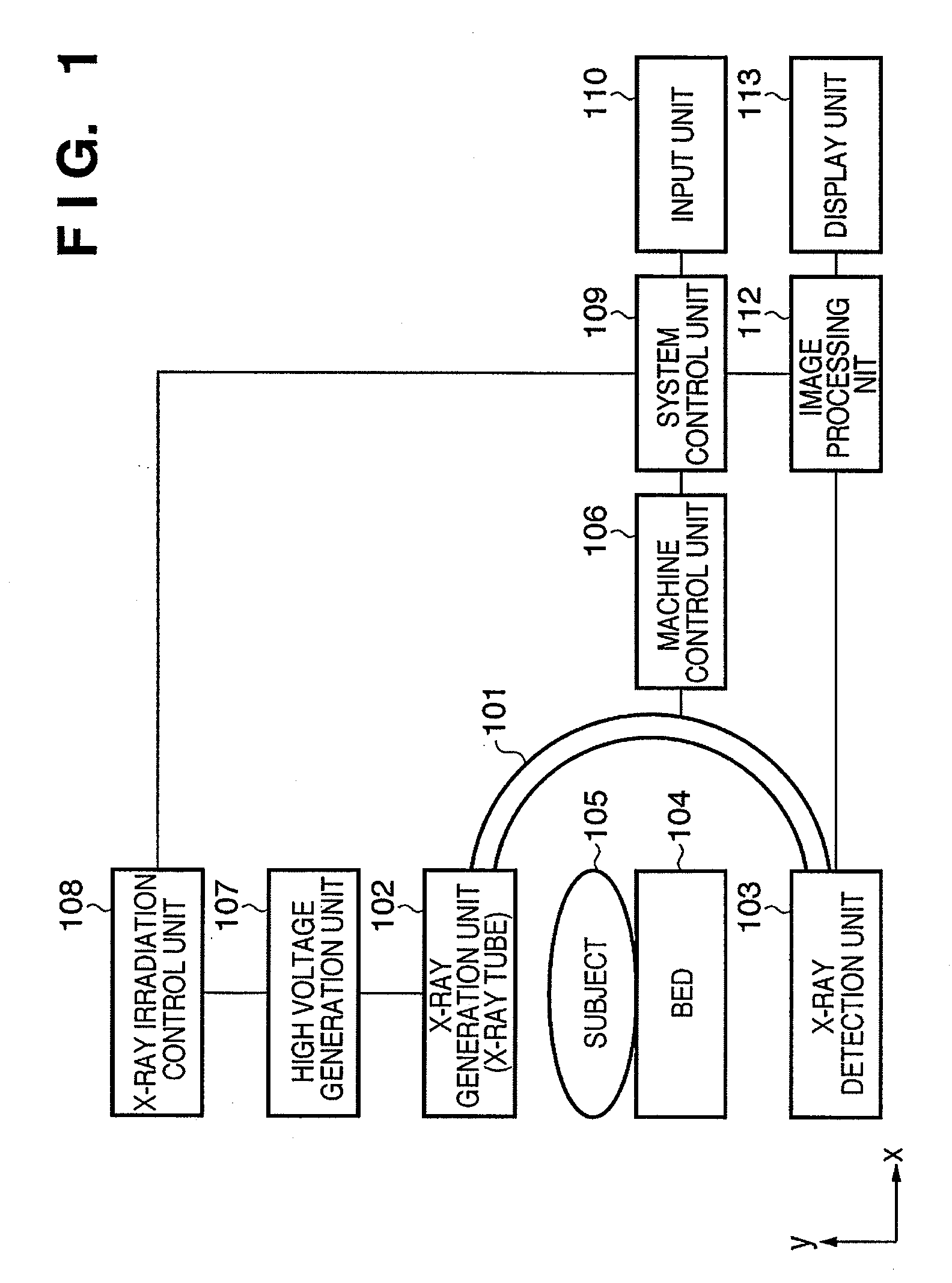
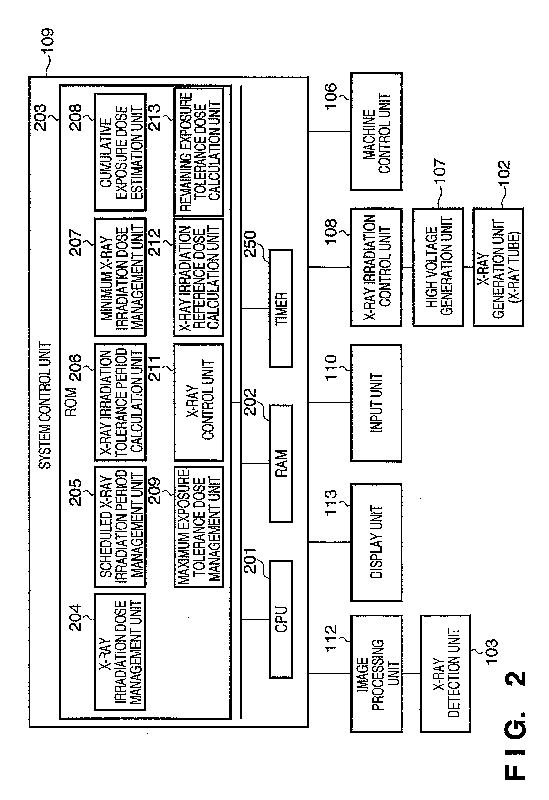
[0022]FIG. 1 shows an example of the configuration of an X-ray imaging apparatus according to the present invention. An X-ray generation unit (X-ray tube) 102 is an X-ray generation source that irradiates X-rays onto a subject (object) 105. The X-ray generation unit (X-ray tube) 102 is held by one end of a holding unit 101. An X-ray detection unit 103 is a sensor that detects X-rays irradiated from the X-ray generation unit (X-ray tube) 102. The X-ray detection unit 103 is held by the other end of the holding unit 101. The X-ray detection unit 103 and the X-ray generation unit (X-ray tube) 102 are held facing one another by the holding unit 101. Note that apart from being fixed, the X-ray detection unit 103 and the X-ray generation unit (X-ray tube) 102 may be held in a state where they are movable relative to one another, provided they continue to face one another.

[0023]A bed 104 is provided between the X-ray generation unit (X-ray tube) 102 ...

second embodiment

[0070]FIGS. 5A and 5B are flowcharts illustrating the operation flow of the X-ray imaging apparatus according to a second embodiment, with the operations of the steps being executed under the overall control of the CPU 201. The X-ray imaging apparatus is assumed to have a similar configuration to FIGS. 1 and 2 described in the first embodiment.

[0071]In step 501, the CPU 201 starts this process.

[0072]In step 502, the CPU 201 determines whether a trigger for starting irradiation has been input. In step 503, the X-ray generation unit 102 performs X-ray irradiation based on the X-ray irradiation dose per unit time held by the X-ray irradiation dose management unit 204.

[0073]In step 504, the CPU 201 determines whether to set the X-ray irradiation dose per unit time manually or automatically (auto X-ray control), based on a selection operation by the operator. If auto X-ray control is instructed by the operation of the operator (S504:YES), the processing proceeds to step 505.

[0074]In step...

third embodiment

[0089]FIGS. 7A and 7B are flowcharts illustrating the operation flow of the X-ray imaging apparatus according to a third embodiment, with the operations of the steps being executed under the overall control of the CPU 201. The X-ray imaging apparatus is assumed to have a similar configuration to FIGS. 1 and 2 described in the first embodiment.

[0090]In step 701, the CPU 201 starts this process.

[0091]In step 702, the CPU 201 determines whether a trigger signal for starting irradiation has been input. In step 703, the X-ray generation unit 102 performs X-ray irradiation based on the X-ray irradiation dose per unit time held by the X-ray irradiation dose management unit 204.

[0092]In step 704, the CPU 201 determines whether an instruction for calculation of the X-ray irradiation reference dose per unit time has been given. If an instruction for calculation of the X-ray irradiation reference dose per unit time has been given (S704:YES), the processing proceeds to step 705.

[0093]On the oth...


PUM


Abstract

An X-ray imaging apparatus includes an estimation unit (208) that estimates a cumulative exposure dose of X-rays irradiated onto an object, a remaining exposure tolerance dose calculation unit (213) that calculates a remaining exposure tolerance dose using a difference between a tolerated maximum exposure dose and the cumulative exposure dose, an X-ray irradiation tolerance period calculation unit (206) that calculates an X-ray irradiation tolerance period using a difference between a predetermined scheduled X-ray irradiation period and an actual irradiation period of X-rays irradiated onto the object, an X-ray irradiation reference dose calculation unit (212) that calculates an X-ray irradiation reference dose per unit time that will form a basis of X-ray irradiation based on the remaining exposure tolerance dose and the X-ray irradiation tolerance period, and a control unit (211) that controls X-ray irradiation onto the object by setting an X-ray irradiation dose per unit time within the X-ray irradiation tolerance period based on the X-ray irradiation reference dose.

Description

BACKGROUND OF THE INVENTION[0001]1. Field of the Invention[0002]The present invention relates to an X-ray imaging technique for preventing patients from being exposed to excessive doses of radiation.[0003]2. Description of the Related Art[0004]X-ray diagnostic imaging utilizing X-rays has typically been applied in radiographic interpretation using still images, although in recent years its application has expanded to include X-ray fluoroscopic examination and surgical support. However, X-ray fluoroscopic examination and surgical support, while being extremely beneficial, unavoidably expose patients to radiation, and the exposure risk must always be taken into consideration when performing X-ray diagnosis and surgical support. Despite these risks, the X-ray dose has heretofore typically been adjusted manually by the operator providing the medical care. The operator selects the appropriate X-ray dose, with regard to the surgical objective, examination application, examination site, th...

Claims


Application Information

Patent Timeline
IPC IPC(8): H05G1/42
CPCA61B6/4441A61B6/542
Inventor INUGA, MIHOYOSHIDA, TAKASHI
Owner CANON KK
Why Eureka
Try Eureka