Particle beam irradiation apparatus, treatment planning unit, and particle beam irradiation method

a particle beam and irradiation apparatus technology, applied in the field of particle beam treatment system, can solve the problems of malfunction or failure, difficulty in perfect elimination of possibility, and the above-described conventional art does not particularly consider such abnormalities or input errors, so as to prolong the treatment time for patients and shorten the treatment time

Active Publication Date: 2006-02-02
HITACHI LTD
View PDF4 Cites 3 Cited by
  • Summary
  • Abstract
  • Description
  • Claims
  • Application Information

AI Technical Summary

Benefits of technology

[0016] In the present invention, the controller controls the charged particle beam scanning unit to perform irradiations of the charged particle beam with respect to at least one irradiation position a plurality of times. By virtue of this feature, regarding an irradiation position subjected to too much irradiation dose by one-time ion irradiation, it is possible to perform a divided irradiation so as to reduce an irradiation dose for each radiation. This allows the difference in irradiation dose between the irradiation position subjected to the largest dose and that subjected to the smallest dose to be reduced, thereby leveling off irradiation dose. As a result, the capacity of the capacitor of a position monitor can be correspondingly reduced to enhance the resolution, and therefore, the actual irradiation dose during treatment can be detected further correctly.
[0019] In the present invention, the controller can perform an irradiation of the charged particle beam to an irradiation position so that the irradiation dose at the irradiation position becomes a set irradiation dose, in a state where the irradiation dose applied to the irradiation position during the time period from the outputting of a beam extraction stop signal up to the extraction stop of the charged particle beam from the accelerator, is added. This allows the irradiation dose at each irradiation position to become substantially the set irradiation dose, thereby enabling the charged particle beam to be applied to each irradiation position with high accuracy. To control the irradiation dose, even if there is time delay between the outputting of the beam extraction stop signal and the extraction stop of the charged particle beam from the accelerator, the irradiation dose at each irradiation position can be made to be a set irradiation dose, allowing for the irradiation dose for the time period during the time delay. This makes it possible to irradiate, with high degree of accuracy, any irradiation position with charged particle beams of a dose substantially equal to the set irradiation dose.
[0021] In the present invention, the controller determines the occurrence of an abnormality based on an elapsed time from the irradiation start of the charged particle beam with respect to one irradiation position. Therefore, even if the irradiation time of the charged particle beam is likely to abnormally elongate due to the occurrence of a malfunction or failure of the irradiation dose detector, or an improper input value, the irradiation of the charged particle beam can be stopped after a certain time has elapsed. This reliably prevents an excessive irradiation to a target, and further improves the safety.
[0023] In the present invention, the controller determines the occurrence of an abnormality, using the irradiation dose detected by the irradiation dose detector and the second set dose larger than respective first set doses with respect to a plurality of irradiation positions in the target. Therefore, even if, due to a malfunction or the like of the beam stopping function, the charged particle beam does not readily stop and the irradiation dose is likely to abnormally increase, the irradiation can be stopped at a certain upper limit irradiation dose, thereby reliably preventing an excessive irradiation to the target. This further enhances the safety.
[0025] In the spot scanning irradiation according to the present invention, as the size of a target changes, the number of spots in a layer changes, and consequently, the time required to complete an irradiation to all spots in the layer changes. Regarding the allowable extraction period of the synchrotron, if it is set to be long with a large target assumed, the irradiations to all layers takes much time to complete, thereby elongating the treatment time for a patient. In the present invention, after the irradiation in a layer region has been completed, the charged particle beam in the accelerator is decelerated, and therefore, the allowable extraction period of the charged particle beams in the accelerator can be earlier terminated. As a result, even when it is necessary to irradiate a plurality of layer regions with charged particle beams, the treatment time can be made short.

Problems solved by technology

However, the aforesaid conventional art does not particularly give consideration to the above-described reduction of the difference in irradiation dose, thus leaving room for improvement in the detection accuracy with respect to the actual irradiation dose.
Since the irradiation dose monitor is an machine, it is difficult to perfectly eliminate the possibility that the irradiation dose monitor causes a malfunction or failure.
However, the above-described conventional art does not particularly give consideration to such a monitor abnormality or an input error.
However, the above-described conventional art does not particularly take a malfunction of such a beam stopping function into consideration.

Method used


Image

  • Particle beam irradiation apparatus, treatment planning unit, and particle beam irradiation method
  • Particle beam irradiation apparatus, treatment planning unit, and particle beam irradiation method
  • Particle beam irradiation apparatus, treatment planning unit, and particle beam irradiation method

Examples


Embodiment Construction

[0045] Hereinafter, a particle beam treatment system having a particle beam irradiation apparatus according to an embodiment of the present invention will be described with reference to the accompanying drawings.

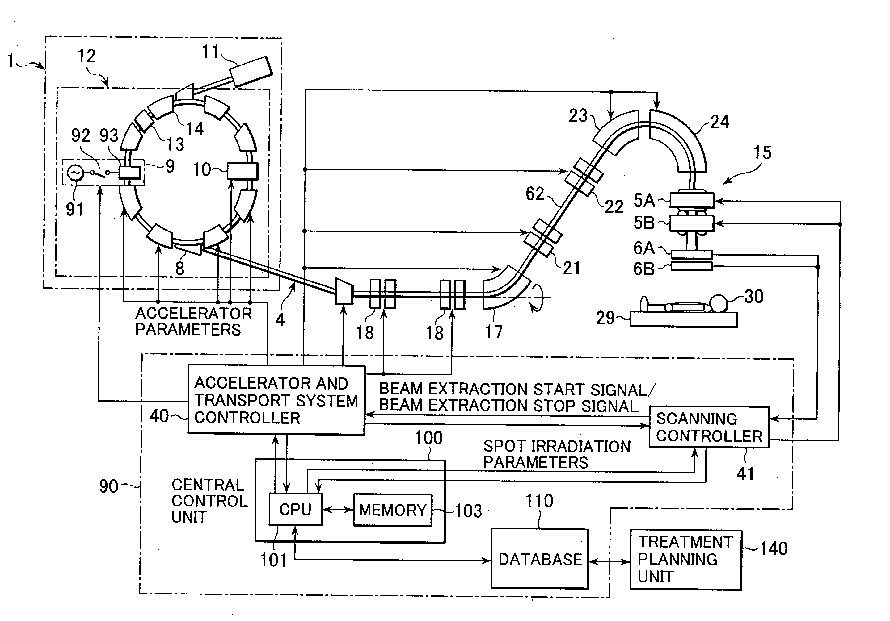
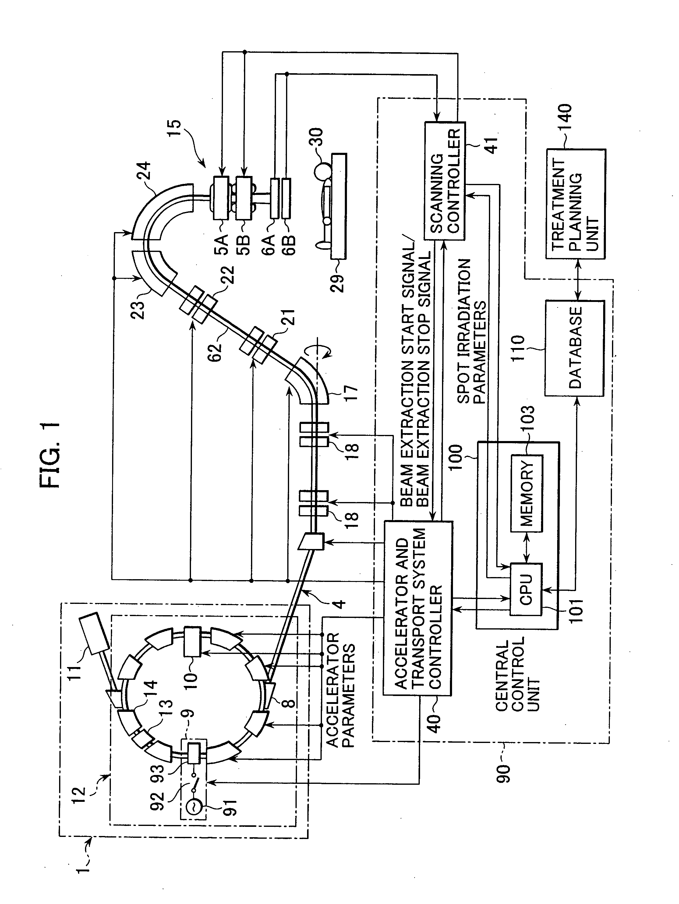
[0046] As shown in FIG. 1, a proton beam treatment system, which is a particle beam treatment system according to this embodiment, includes a charged particle beam generating unit 1 and a beam transport system 4 connected to the downstream side of the charged particle beam generating unit 1.

[0047] The charged particle beam generating unit 1 comprises an ion source (not shown), a pre-stage charged particle beam generating unit (linear accelerator (linac)) 11, and a synchrotron (accelerator) 12. The synchrotron 12 includes a high-frequency applying unit 9 and acceleration unit 10. The high-frequency applying unit 9 is constructed by connecting a high-frequency applying electrode 93 disposed on the circulating orbit of the synchrotron 12 and a high-frequency power source 91 b...


PUM


Abstract

A particle beam irradiation apparatus includes a synchrotron, two scanning electromagnets, an beam delivery apparatus for outputting an ion beam extracted from the synchrotron, and an accelerator and transport system controller, and a scanning controller. These controllers stop the output of the ion beam from the beam delivery apparatus; in a state where the output of the ion beam is stopped, change the irradiation position of the ion beam by controlling the scanning electromagnets; and after this change, control the scanning electromagnets to start the output of the ion beam from the beam delivery apparatus and to perform irradiations of the ion beam to at least one irradiation position a plurality of times based on treatment planning information.

Description

BACKGROUND OF THE INVENTION [0001] 1. Field of the Invention [0002] The present invention relates to a particle beam treatment system, and more particularly to a particle beam irradiation apparatus for treating an affected part by irradiating it with charged particle beams comprising proton ions, carbon ions, or the like, and a treatment planning unit using this particle beam irradiation apparatus, and a particle beam irradiation method. [0003] 2. Description of the Related Art [0004] A treatment method for treating a patient with cancer or the like by irradiating the affected part of the patient with charged particle beams such as proton beams is known. The treatment system used for this treatment includes a charged particle beam generating unit, beam transport system, and treatment room. The charged particle beam accelerated by the accelerator of the charged particle beam generating unit reaches the beam delivery apparatusbeam delivery apparatus in the treatment room through the b...

Claims


Application Information

Patent Timeline
Patent Type & Authority Applications(United States)
IPC IPC(8): G21G4/00G21K1/093A61N5/10G21K1/08G21K5/00G21K5/04H05H13/04
CPCA61N5/10A61N5/1042A61N5/1043A61N2005/1087A61N5/1044G21K5/04H05H7/04H05H7/10G21K1/08
Inventor MATSUDA, KOJINAKAYAMA, TAKAHIDE
Owner HITACHI LTD
Why Eureka
Try Eureka