Plastic Material Moulding Apparatus, in Particular for Moulding Vehicle Body Parts

Inactive Publication Date: 2008-12-25
ILMA PLASTICA
View PDF15 Cites 3 Cited by
  • Summary
  • Abstract
  • Description
  • Claims
  • Application Information

AI Technical Summary

Benefits of technology

[0006]In this way, the apparatus according to the invention allows a significant reduction of the number of components and a simplified construction with respect to the known solutions; the apparatus according to the invention is therefore relatively s

Problems solved by technology

A relatively high number of mechanical components, a relatively complex movement systems and relative large movement members are required; consequently, also the apparatus as a whole has considerable size and dimensions.
The apparatuses of this type are consequently complicated (and costly) and cumbersome.
Furtherm

Method used


Image

  • Plastic Material Moulding Apparatus, in Particular for Moulding Vehicle Body Parts
  • Plastic Material Moulding Apparatus, in Particular for Moulding Vehicle Body Parts
  • Plastic Material Moulding Apparatus, in Particular for Moulding Vehicle Body Parts

Examples


Embodiment Construction

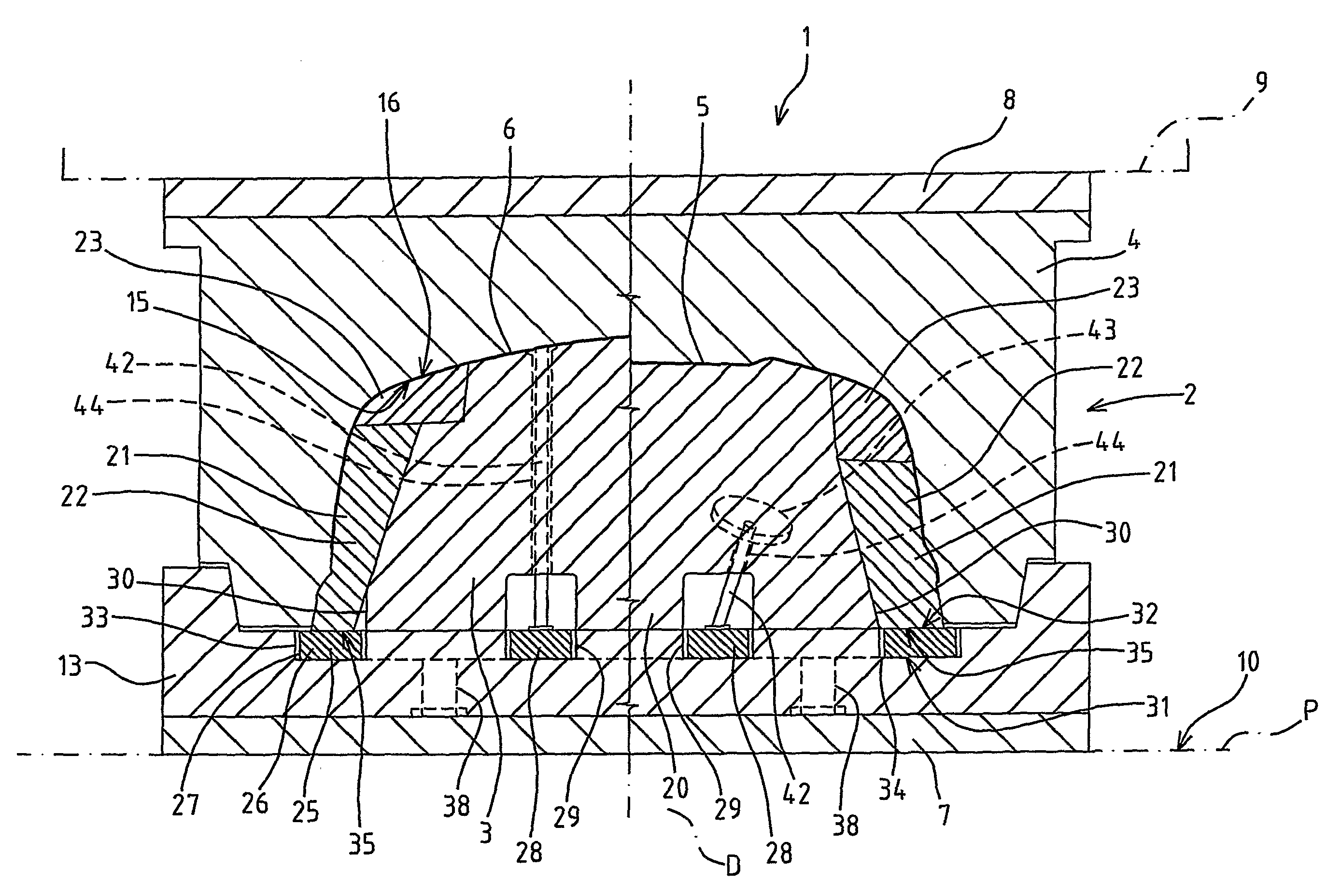
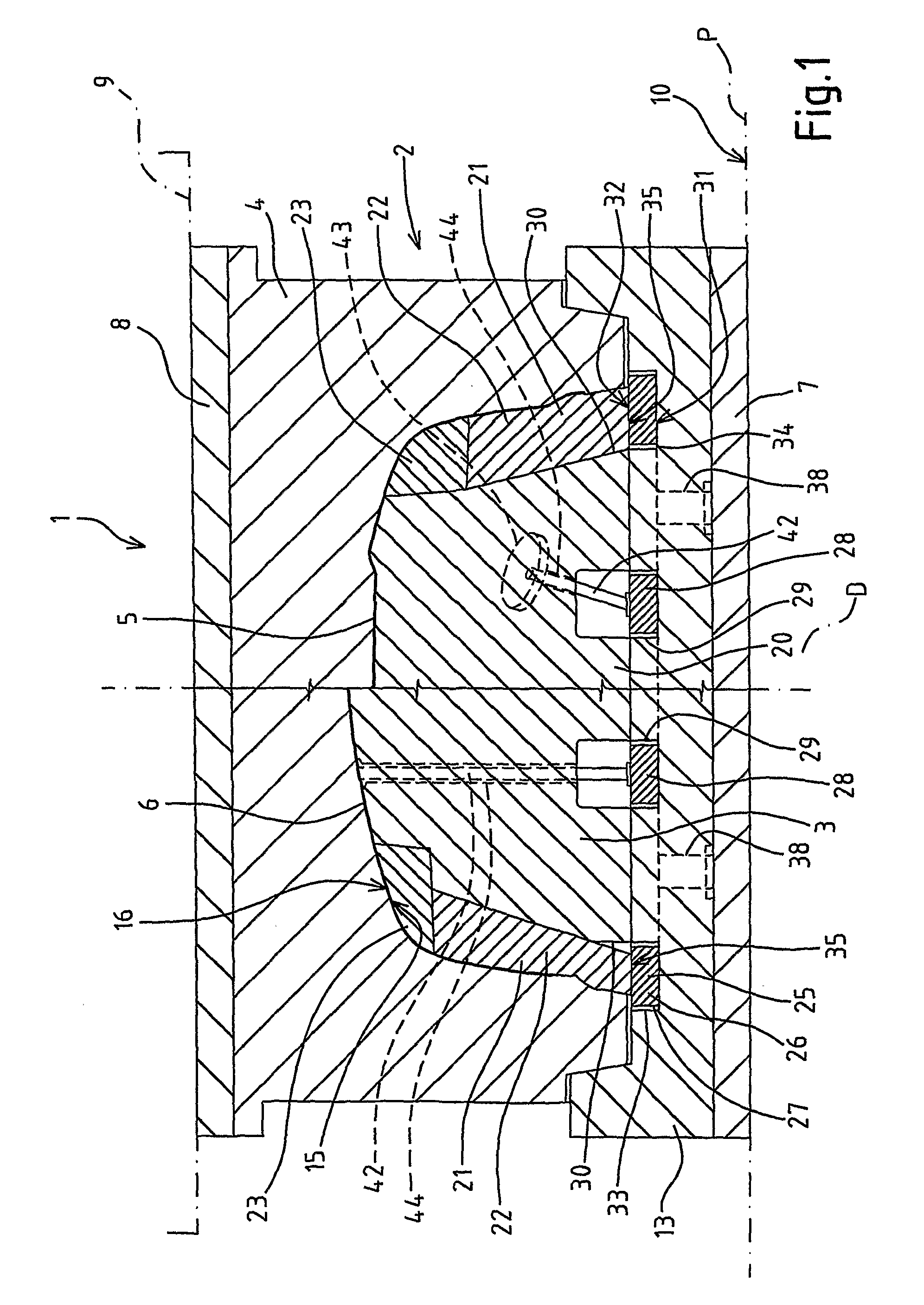
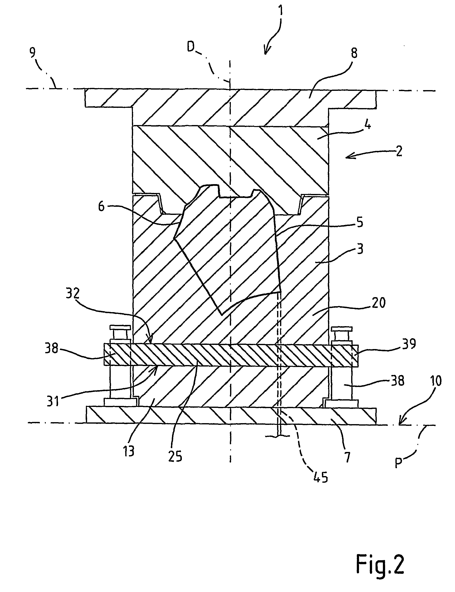
[0012]In FIGS. 1 and 2, number 1 indicates as a whole a plastic material moulding apparatus, in the case in point an injection moulding apparatus for vehicle body parts, such as for example bumpers, spoilers, etc.

[0013]Apparatus 1 comprises a mould 2, formed by a punch 3 and a matrix 4, cooperating with each other to define a cavity 5 having the shape of a piece 6 to be moulded; punch 3 and matrix 4 are integrally connected to respective substantially flat and parallel bottom plates 7, 8, intended in use to cooperate with respective parts of a press 9 (known and not shown in detail for the sake of simplicity). In particular, bottom plate 7 rests on a surface 10 of press 9 defining a reference press-plate P.

[0014]Punch 3 is carried by a punch-carrier element 13 fixed to bottom plate 7; matrix 4 is directly fixed to bottom plate 8. Punch 3 overhangingly projects from punch-carrier element 13 and is inserted in a corresponding impression formed in matrix 4; punch 3 and matrix 4 are pro...


PUM


Abstract

A plastic material moulding apparatus, in particular for moulding vehicle body parts, includes a mould consisting of a punch and a matrix, cooperating with each other to define a cavity having the shape of a piece to be moulded and movable with respect to each other; a bottom plate which integrally carries a fixed body of the punch, and an extractor element, supported by the bottom plate and movable with respect to the bottom plate and to the body along a sliding direction; the extractor element is closed in a loop to define an extraction ring arranged substantially around the fixed body of the punch and shaped so as not to interfere, while moving along the sliding direction, with the body.

Description

TECHNICAL FIELD[0001]The present invention relates to a plastic material moulding apparatus, in particular for moulding vehicle body parts.BACKGROUND ART[0002]As known, moulded plastic material components are increasingly common in the automotive sector, in particular for making body parts, such as for example bumpers, wheelhouses, spoilers, etc.[0003]These components are usually injection moulded in moulding apparatuses which, in general terms, comprise a mould formed by a matrix and a punch carried by respective bottom plates; the punch comprises a fixed body, integrally connected to the bottom plate by means of a punch-carrier element, and parts (punch headers and internal inserts) which are movable with respect to the fixed body. To allow the extraction of the moulded piece, the apparatus comprises an extraction plate, movable with respect to the punch, which carries a plurality of movement members (bars, mechanical carriages, etc.), having very complex geometries and mechanisms...

Claims


Application Information

Patent Timeline
IPC IPC(8): B29C45/40
CPCB29C33/442B29C45/4005B29C45/4421B29C2045/4057B29C2045/4078B29L2031/3005
Inventor VOLPONI, LEONARDO
Owner ILMA PLASTICA
Why Eureka
Try Eureka