
Massage Tool

a massage tool and tool body technology, applied in the field of massage tools, can solve the problems of high production cost, user unwillingness to buy, waste of assembly time, etc., and achieve the effect of convenient assembly of parts, convenient assembly of toes and magnets, and simplified assembly structur

Inactive Publication Date: 2008-12-25
CHUEN JEOU DAY ENTERPRISE
View PDF2 Cites 37 Cited by
  • Summary
  • Abstract
  • Description
  • Claims
  • Application Information

AI Technical Summary

Benefits of technology

[0031]The advantage of the invention: The massage tool of the invention, which uses a new assembly of barrel and handle, to simplify the assembly structure, and easier the assemble of the toe and magnet. The massage tool of the invention, wherein the assembly of the part is convenient, and the assembled structure is stronger. The massage tool of the invention, which has a plurality of magnets, when using the massage tool to massaging, still has the magnetic effect produced by the magnets.
[0032]The massage tool of the invention not only can using the finger to solve the problem of aches, but also the magnets further improved blood circulation of human body, to achieve the object of health care.

Problems solved by technology

But there are many problems in manufacturing method of the prior tool, and the structure is complicated, causing waste time of assembly and higher the cost of the production, and the user is not willing to buy.

Method used


Image

  • Massage Tool
  • Massage Tool
  • Massage Tool

Examples


first embodiment

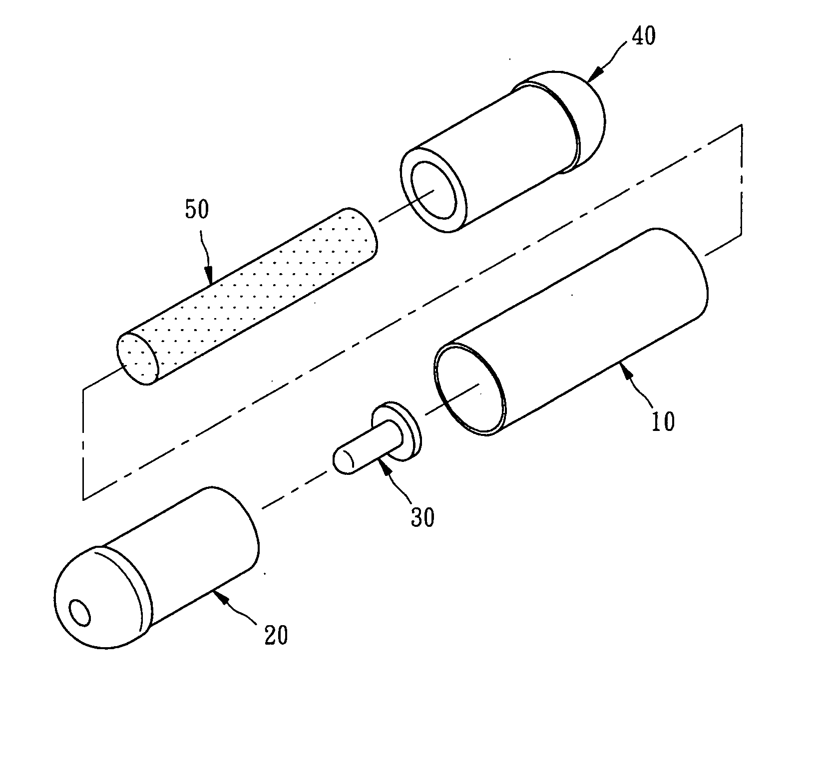
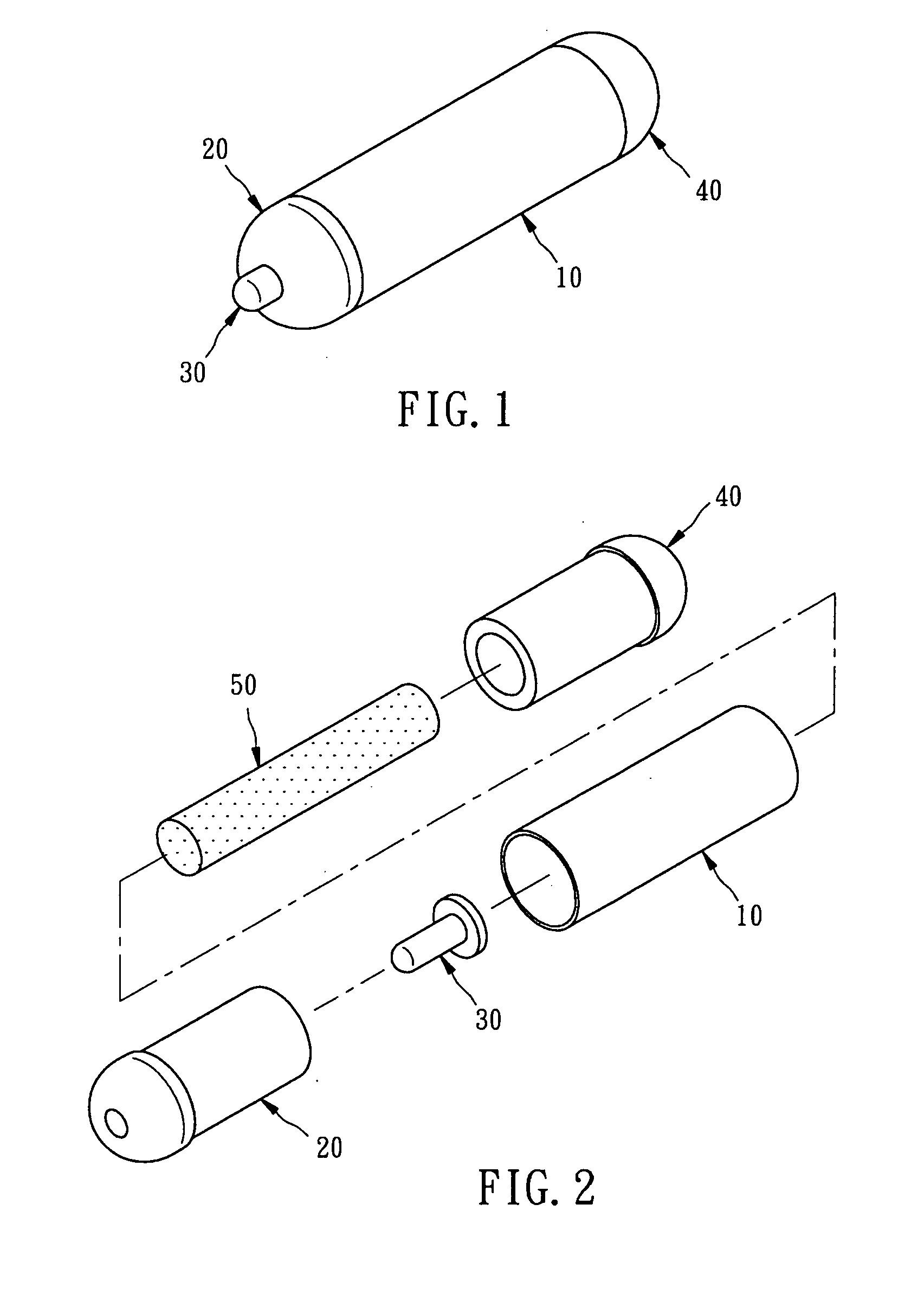
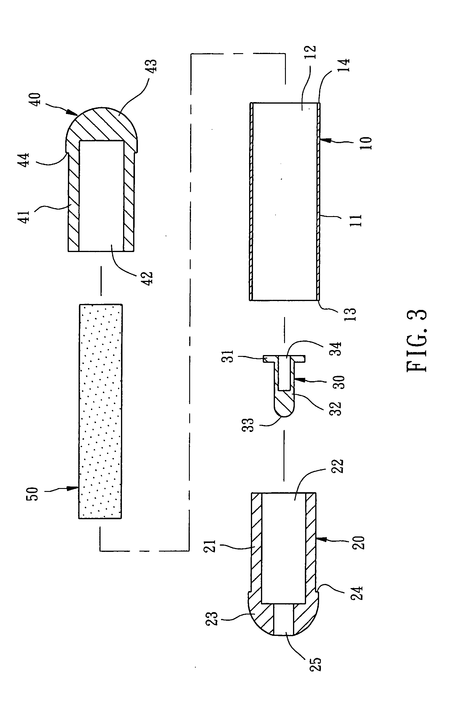
[0050]Please refer FIG. 1 to FIG. 4, a massage tool of the invention comprises the follows:

[0051]A handle 10 has a cylinder 11 being held by hand, a barrel hole 12 going through the cylinder 11, a first rim 13 and a second rim 14 formed at two sides of the cylinder 11 respectively.

[0052]A first barrel 20 has a barrel body 21 inserted into the barrel hole 12 of the handle 10, a chamber 22 concaved formed from the first barrel 20 upwards and formed of a loop section, a barrel end 23 formed on the barrel body 21, a rim 24 stopped against the first rim 13 of the handle 10, a fitting hole 25 opened through the chamber 22 bottom.

[0053]A toe 30 has a shoulder 31, a toe post 32 being inserted through the fitting hole 25 of the first barrel 20, the toe post 32 formed a semi-spherical shape at top, a toe head 33 protruded from the toe 30, a chamber 34 formed at the bottom of the toe 30, the chamber 34 concaved formed from the toe 30 bottom upwards and formed of a loop section.

[0054]A second b...

second embodiment

[0058]First, as shown in FIG. 5, shows the invention; wherein the quantity of the magnets 50A is three, each magnet 50A arranged by different pole adjacent to each other.

third embodiment

[0059]Further, as shown in FIG. 6, the invention is substantially same as above embodiment, wherein the first barrel formed an inner thread 27B, the toe formed an outer thread 37B threaded to the inner thread 27B of the first barrel, then the toe can thread with the first barrel.


PUM


Abstract

A massage tool includes a handle, which has a cylinder provided for holding, a barrel hole going through the cylinder; a first barrel, which has a barrel body inserted into the barrel hole of the handle, a chamber formed concaved on the barrel body, a fitting hole opened downwards from the bottom of the chamber; a toe, which has a shoulder received in the chamber of the first barrel; a second barrel, which has a barrel body inserted into the barrel hole of the handle; the massage tool which assembled via above structure is convenient for use and holding; further, the massage tool can includes a skirt, which has a skirt body mounted on the handle, the second barrel and the skirt mounted at least two fingers or a palm; and a magnet group received in the chamber of the first barrel; thereby, the invention can assembled variety of massage tool, the magnet group generating magnetic field improve human body blood circulation, and the toe or the finger to proceed pressing.

Description

FIELD OF THE INVENTION[0001]The present invention relates to tools of massage and more specifically, to a massage tool.DESCRIPTION OF THE RELATED ART[0002]The structure of prior massage tool, commonly comprise a cylinder body, two caps, a toe, and a plurality of magnets, wherein the cylinder body is provided mounting of each cap, the toe mounted on one of the two caps, each magnet can be received inside the chamber which formed by each cap assembled with the cylinder body, then get the massage tool.[0003]But there are many problems in manufacturing method of the prior tool, and the structure is complicated, causing waste time of assembly and higher the cost of the production, and the user is not willing to buy.SUMMARY OF THE INVENTION[0004]The main object of the massage tool of the invention, which uses a new assembly of barrel and handle, to simplify the assembly structure, and easier the assemble of the toe and magnet.[0005]Another object of the massage tool of the invention, wher...

Claims


Application Information

Patent Timeline
Patent Type & Authority Applications(United States)
IPC IPC(8): A61F2/06
CPCA61H39/04A61H2201/10A61N2/06A61N2/12
Inventor LAI, TZN-YUNG
Owner CHUEN JEOU DAY ENTERPRISE
Learn More