
Surgical irrigator

a technology of irrigator and irrigator, which is applied in the field of surgical irrigator, can solve the problems of less than optimum flexibility in use, poor grip of large handgrips, and inability to easily grip large handgrips, so as to reduce the quantity of equipment and control

Inactive Publication Date: 2008-12-25
BIDOIA S DI GIANFRANCO BIDOIA E C
View PDF25 Cites 2 Cited by
  • Summary
  • Abstract
  • Description
  • Claims
  • Application Information

AI Technical Summary

Benefits of technology

The design enhances flexibility and ergonomics, maintains pulsed flow during startup and shutdown, reduces equipment clutter, and eliminates battery-related issues, providing a safer and more efficient surgical irrigation experience.

Problems solved by technology

Moreover, these procedures can cause blood losses which must be eliminated or blocked at least partially if not totally.
However, the good ergonomics of the pistol-type device contrasts with the problem of less than optimum flexibility in use, since the limited length of the ejection portion (limited by the “butt”) does not allow to reach deeply into the region to be irrigated or cleaned and is poorly suited in narrow cavities.
Small hands (such as for example female hands or hands of small-built populations) are therefore poorly suited to gripping easily large handgrips.
In any case, both with the pistol-type irrigation device and in the case of the cylindrical shape, the region to be irrigated / cleaned might be hidden by the device itself, making the procedure more difficult.
On the other hand, the use of the peristaltic pump entails the problem that since the hose is highly flexible in order to allow its deformation by the rotors, during the starting and stopping of the pump part of the impulse of the liquid is “lost” in the deformation along the rest of the hose, leading to a continuous and not “pulsed” stream.
Further, due to this deformation, the pressure at startup is uncontrolled and often too high.
Moreover, although these pumps are small, they encumber the area where the operators move, which is often already overloaded with equipment.
The dimensions of the device, however, are larger and therefore flexibility of use in operating cavities is limited with respect to the peristaltic pump.
Further, depending on their charge, the supply of power to the motor is never constant and optimum, with repercussion on the pressure of the flow of the pump.
Moreover, these batteries must be arranged in single-use containers which must be sterilized (in addition to being rather bulky).

Method used


Image

  • Surgical irrigator
  • Surgical irrigator
  • Surgical irrigator

Examples


Embodiment Construction

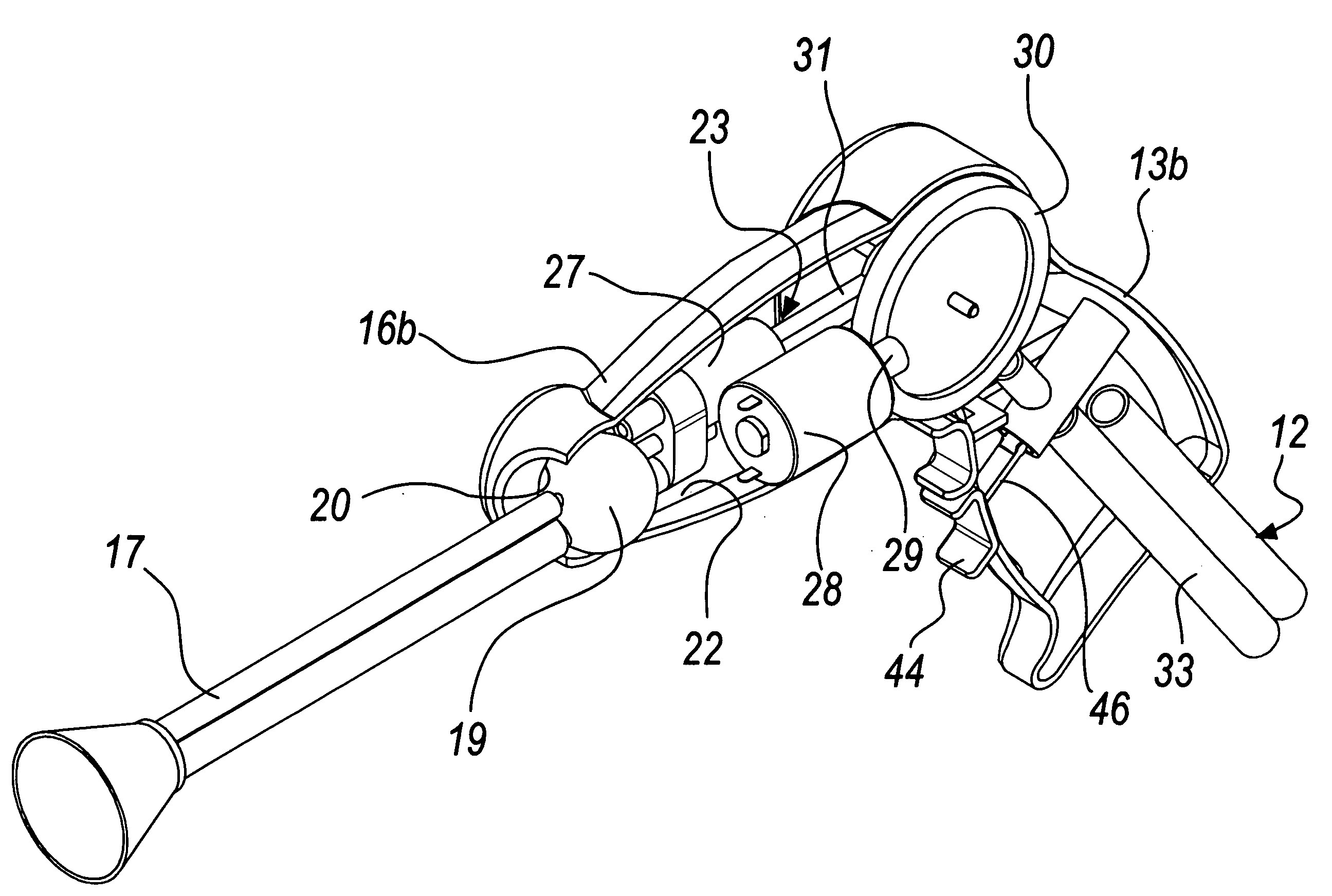
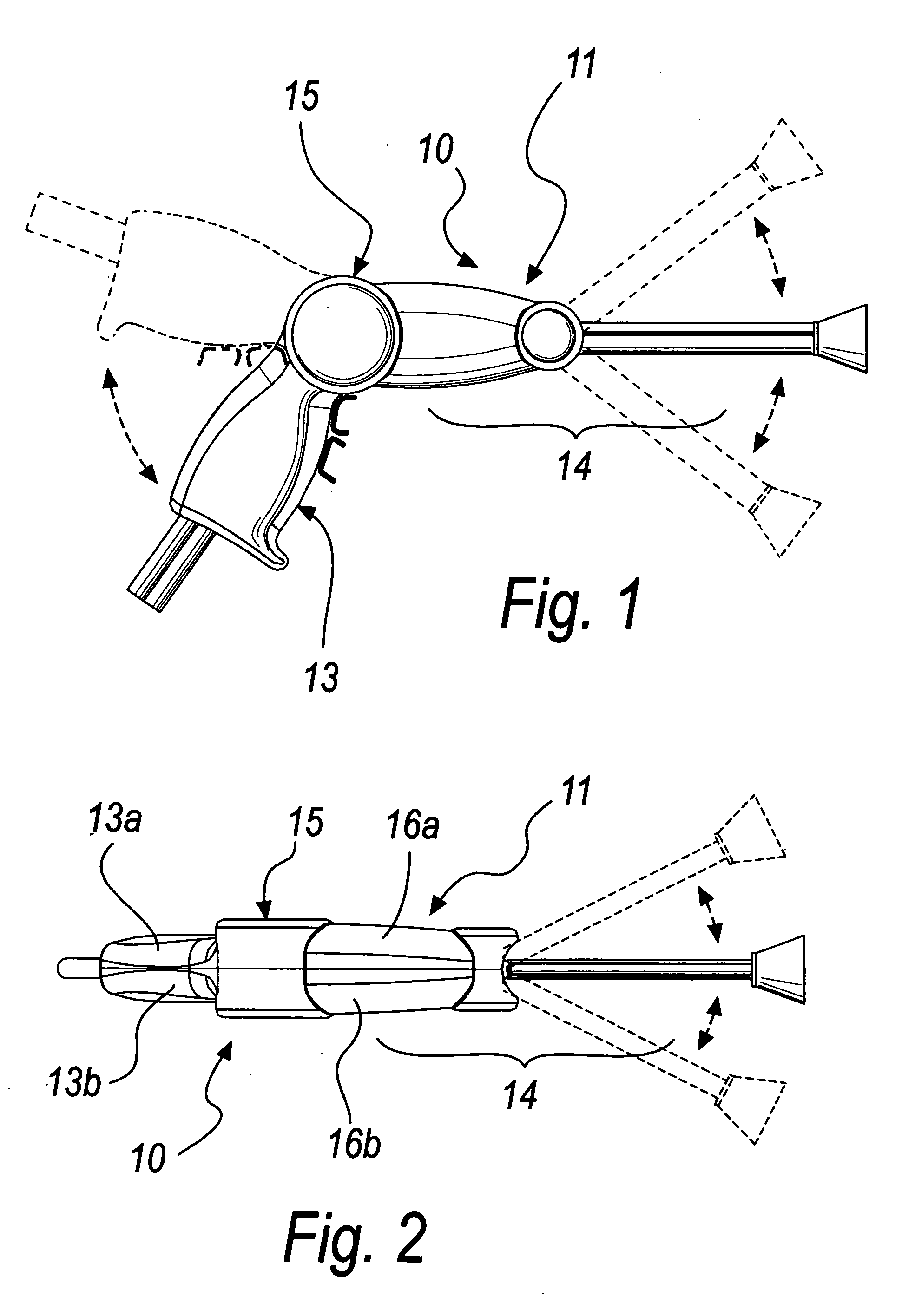
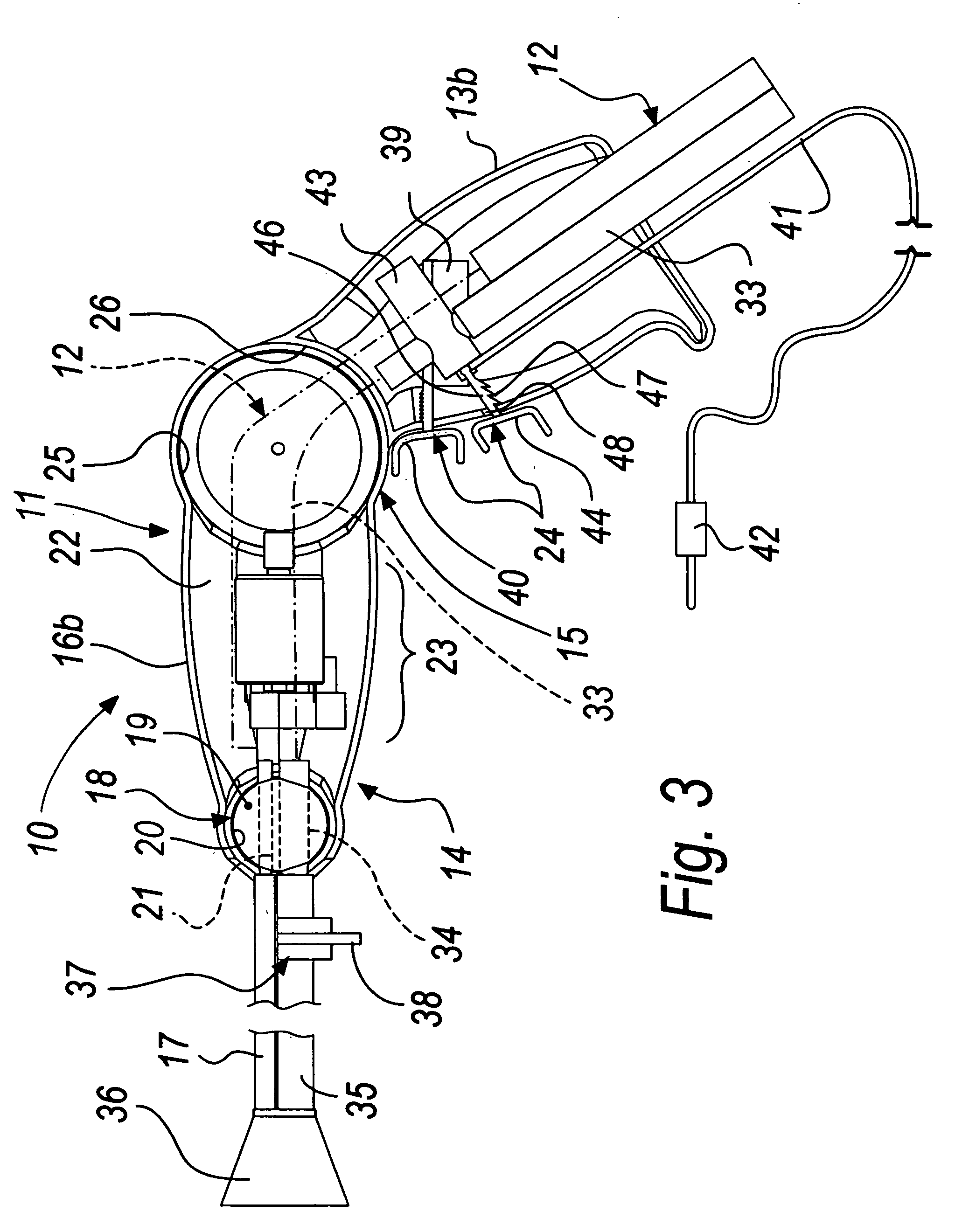
[0062]With reference to the figures, a surgical irrigator for washing body regions subjected to a procedure according to the invention is generally designated by the reference numeral 10.

[0063]The surgical irrigator 10 is constituted by a containment shell 11, inside which there are means 12 for feeding the washing liquid which arrives from an associable reservoir (not shown in the figures), all of which are described in greater detail hereinafter.

[0064]The containment shell 11 is constituted substantially by two distinct portions, respectively a grip portion 13 for the hand of the user and a portion 14 for ejecting the washing liquid toward the region to be washed.

[0065]The grip portion 13 is contoured ergonomically like the butt of a pistol.

[0066]The ejection portion 14 is articulated with friction to the grip portion 13 by way of articulation means 15, described in greater detail hereinafter, about an axis which is perpendicular to the longitudinal axis of the grip portion 15.

[00...


PUM


Abstract

A surgical irrigator for washing body regions subjected to a procedure, provided with a containment shell inside which there are elements for supplying a washing liquid that arrives from an associable reservoir, such containment shell being constituted substantially by two distinct portions, respectively a grip portion for the hand of the user and a portion for ejecting the washing liquid toward the region to be washed, wherein the irrigator is powered by a transformer connected to the mains.

Description

[0001]This is a divisional application of U.S. patent application Ser. No. 11 / 663,181 of Mar. 19, 2007.[0002]The present invention relates to a surgical irrigator for washing body regions subjected to procedures, useful particularly but not exclusively in orthopedic surgery.BACKGROUND OF THE INVENTION[0003]During surgical procedures it is often necessary to clean the operative areas in order to improve the surgeon's view and remove blood loss and other physiological residues.[0004]Physiological residues can be portions of soft tissue, cartilage and bone fragments.[0005]These cleaning operations sometimes need to be rather energetic in order to remove residues that have remained partially attached to the originating part.[0006]At the same time, the energetic action of these cleaning operations can lead advantageously to limited hemostasis in the operative regions.[0007]The need for energetic cleaning actions occurs especially in orthopedic surgery, both for prosthetic procedures and ...

Claims


Application Information

Patent Timeline
Patent Type & Authority Applications(United States)
IPC IPC(8): A61M3/00
CPCA61M1/0064A61M3/0258A61M3/0202A61M1/772
Inventor BIDOIA, GIANFRANCO
Owner BIDOIA S DI GIANFRANCO BIDOIA E C
Learn More