Fluid dispenser with additive sub-system

Inactive Publication Date: 2008-12-25
KRIESEL MARSHALL S +1
View PDF99 Cites 30 Cited by
  • Summary
  • Abstract
  • Description
  • Claims
  • Application Information

AI Technical Summary

Benefits of technology

[0022]Another object of the invention is to provide a fluid dispenser of the class described which is compact and lightweight, is easy for ambulatory patients to use, is fully disposable and is extremely reliable in operation.
[0023]Another object of the invention is to provide a small, compact fluid dispenser th

Problems solved by technology

Such gravametric methods are cumbersome, imprecise and require bed confinement of the patient.
Accordingly, the prior art devices are not well suited for use in those instances where the patient must be transported to a remote facility for treatment.
Drug infusion devices currently available can impede the timely administrat

Method used


Image

  • Fluid dispenser with additive sub-system
  • Fluid dispenser with additive sub-system
  • Fluid dispenser with additive sub-system

Examples


Example

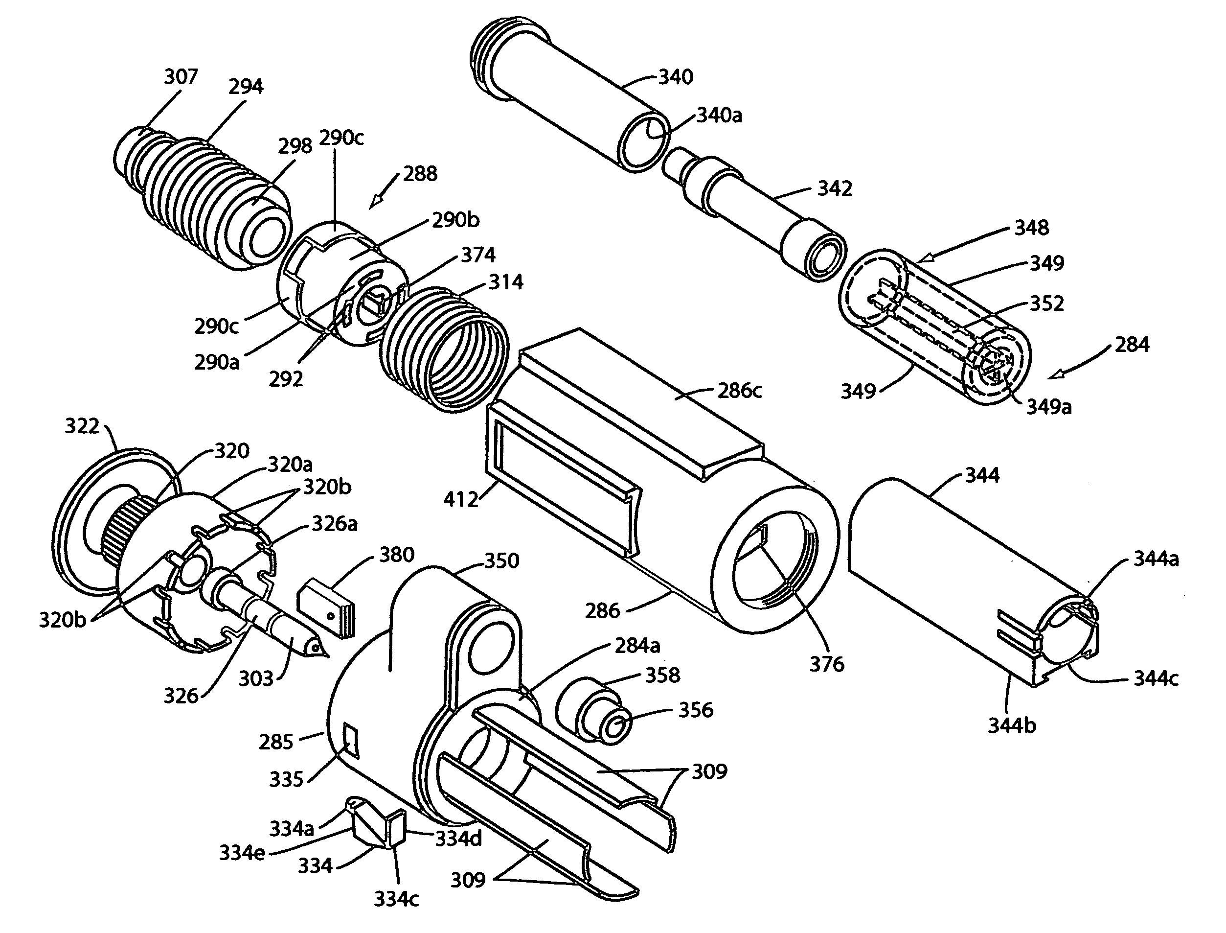
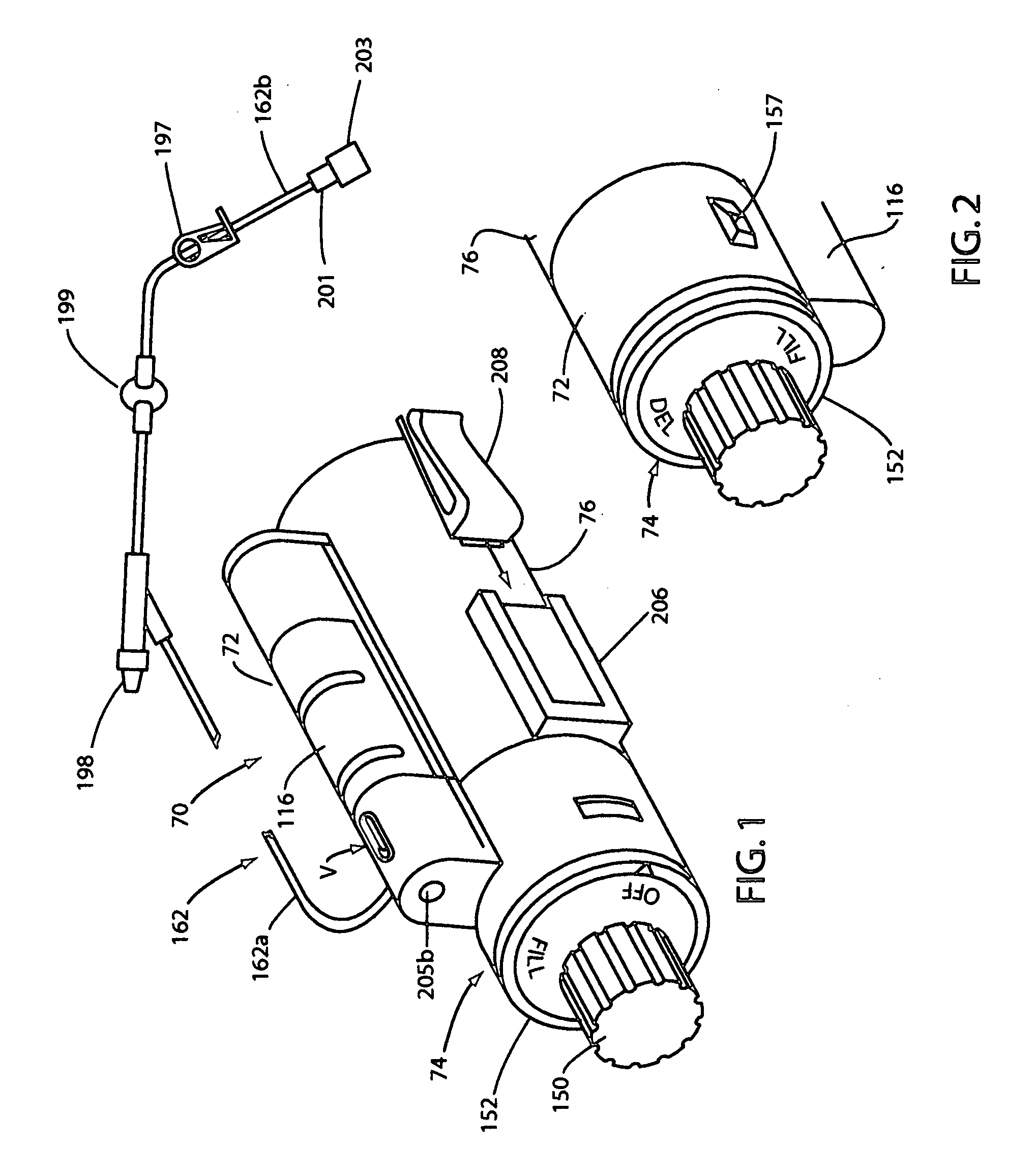
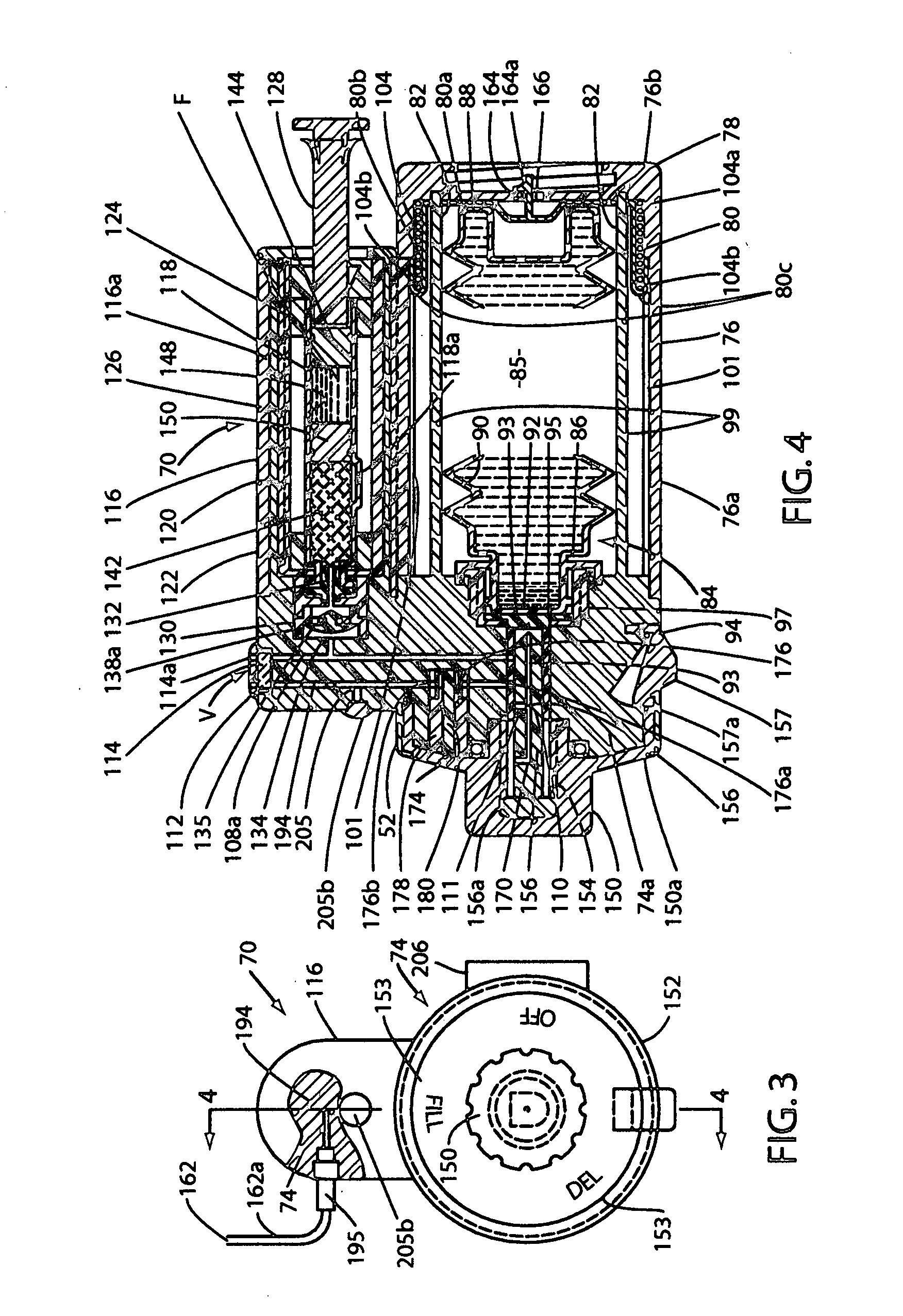
[0120]Referring to the drawings and particularly to FIGS. 1 through 4, one form of the dispensing device of the present invention for dispensing medicaments to a patient is there shown and generally designated by the numeral 70. The dispensing device here includes a housing 72 which includes a control portion 74 and a generally cylindrically shaped reservoir housing 76 that is interconnected with the control portion 74 in the manner best seen in FIG. 4 of the drawings. Housing 72 can be constructed from metal, plastic or any suitable material. Reservoir housing 76 includes a generally cylindrically shaped wall portion 76a and a base portion 76b.

[0121]Disposed within wall portion 76a is a carriage assembly 78 which is movable between a first position shown in FIG. 4 and a second position. As best seen by referring to FIG. 4, carriage assembly 78 comprises a carriage 80 having a carriage base 80a that is provided with a plurality of circumferentially spaced openings 82 and a generall...


PUM


Abstract

A compact fluid dispenser for use in controllably dispensing fluid medicaments, such as, antibiotics, analgesics, and like medicinal agents from the device reservoir which is provided in the form of a novel bellows-type assembly. The fluid dispenser includes a unique stored energy mechanism which takes the form of a constant force spring member of novel design that provides the force necessary to continuously and substantially uniformly expel fluid from the device reservoir. The device also includes novel adjustable flow rate control assembly that is disposed intermediate the fluid reservoir outlet and the outlet port of the device for precisely controlling the rate of fluid flow from the outlet port toward the patient.

Description

[0001]This is a Continuation In Part of co-pending U.S. Ser. No. 11 / 823,084 filed Jun. 25, 2007.BACKGROUND OF THE INVENTION [0002]1. Field of the Invention[0003]The present invention relates generally to fluid dispensing devices. More particularly, the invention concerns medicament dispensers for dispensing medicinal fluids to ambulatory patients.[0004]2. Discussion of the Prior Art[0005]A number of different types of medicament dispensers for dispensing medicaments to ambulatory patients have been suggested in the past. Many of the devices seek either to improve or to replace the traditional gravity flow and hypodermic syringe methods which have been the standard for delivery of liquid medicaments for many years.[0006]The prior art gravity flow methods typically involve the use of intravenous administration sets and the familiar flexible solution bag suspended above the patient. Such gravametric methods are cumbersome, imprecise and require bed confinement of the patient. Periodic ...

Claims


Application Information

Patent Timeline
IPC IPC(8): A61M5/142A61M37/00
CPCA61M5/14244A61M5/148A61M2005/14272A61M2005/14506A61M2209/045
Inventor KRIESEL, MARSHALL S.KRIESEL, JOSHUA W.
Owner KRIESEL MARSHALL S
Why Eureka
Try Eureka