Forwardly directable fluid jet crossing catheter

Inactive Publication Date: 2008-12-25
MEDRAD INC.
View PDF94 Cites 17 Cited by
  • Summary
  • Abstract
  • Description
  • Claims
  • Application Information

AI Technical Summary

Benefits of technology

[0014]Another significant aspect and feature of the present invention is the heat processing of the nitin

Problems solved by technology

Vessel safety testing has shown that vessel damage is associated with the inflow windows rather than the outflow windows.
However, as a clot becomes more aged and organized, the strength of the clot can increase in orders of magnitude an

Method used


Image

  • Forwardly directable fluid jet crossing catheter
  • Forwardly directable fluid jet crossing catheter
  • Forwardly directable fluid jet crossing catheter

Examples


Embodiment Construction

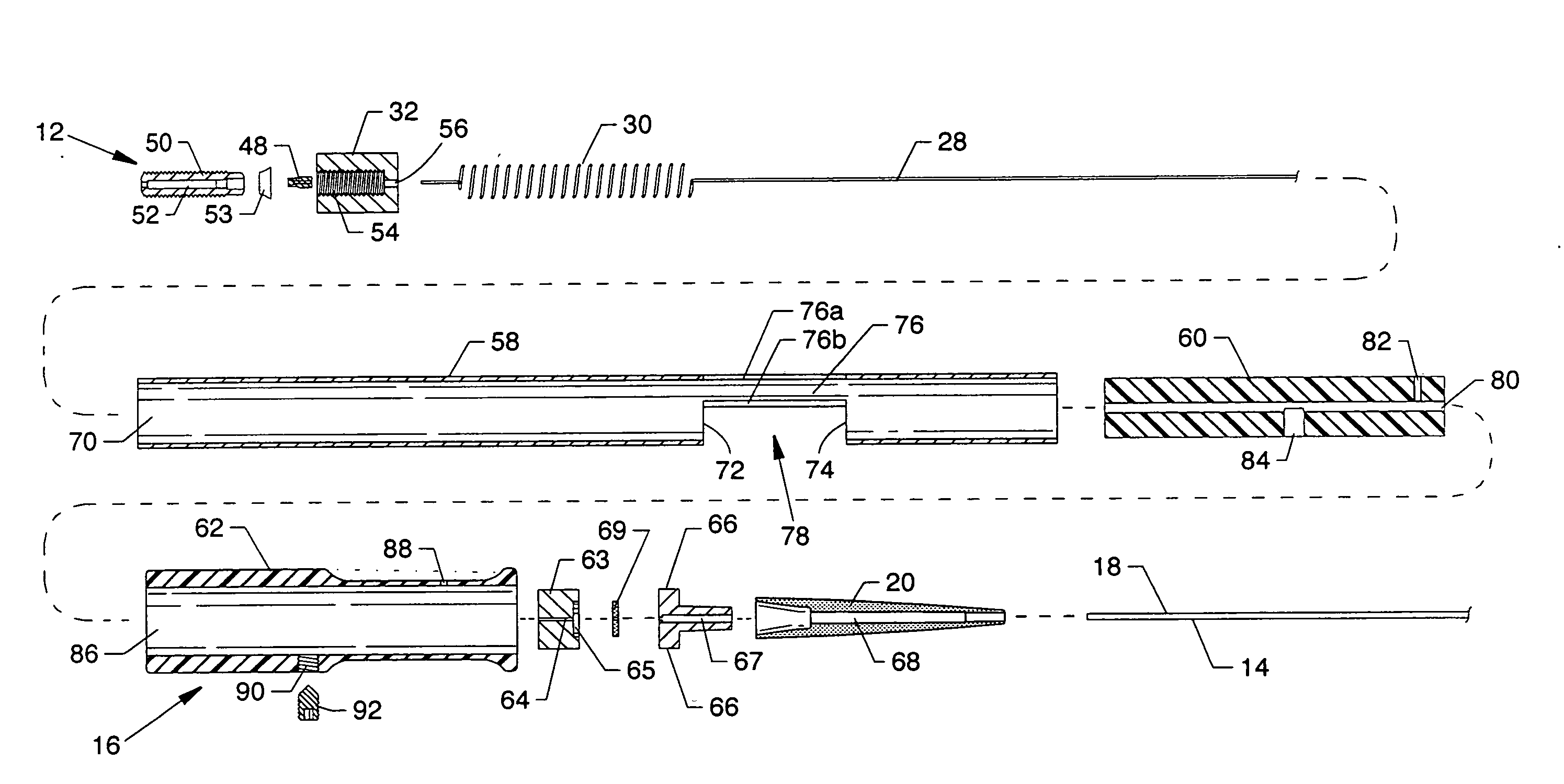
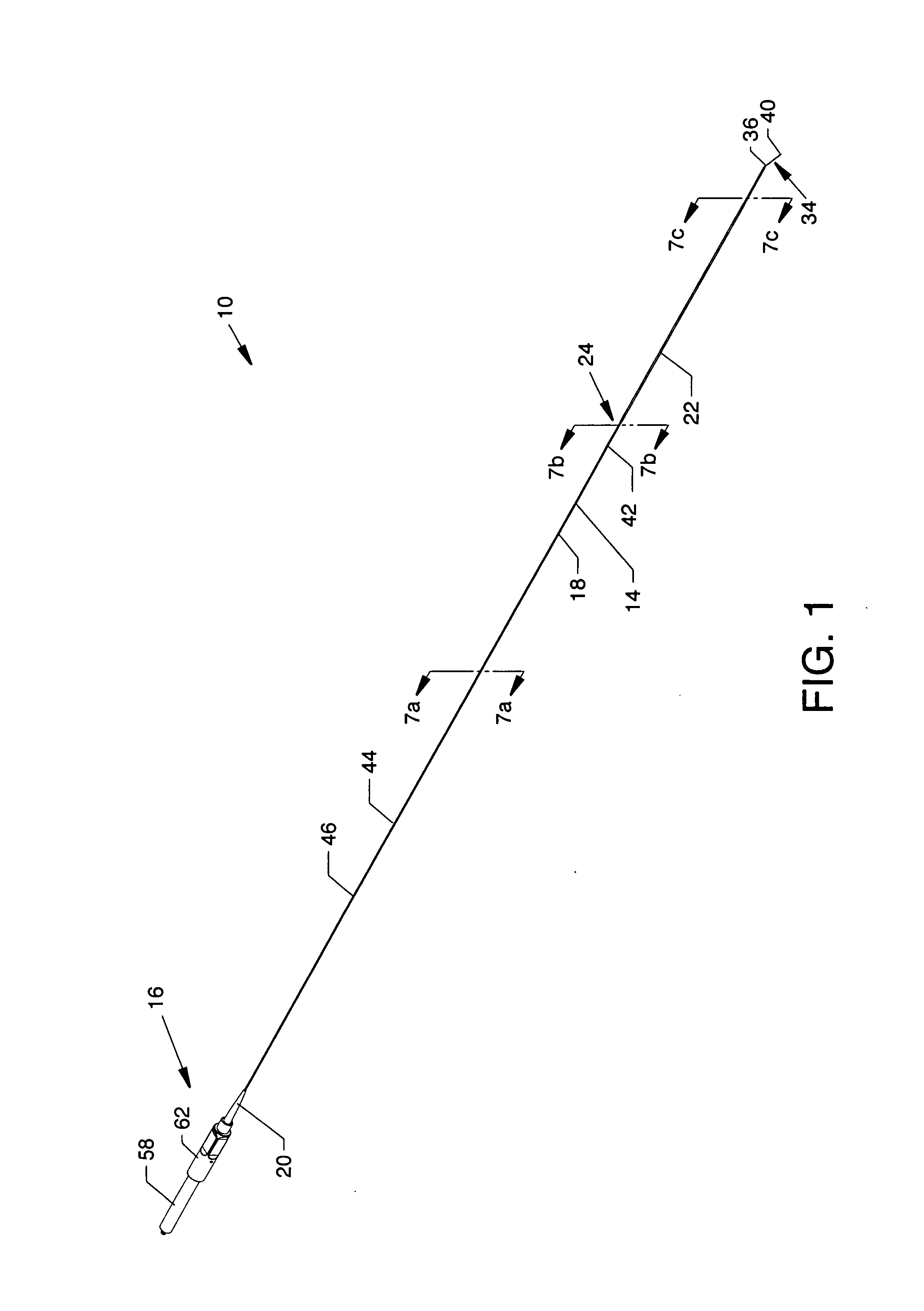
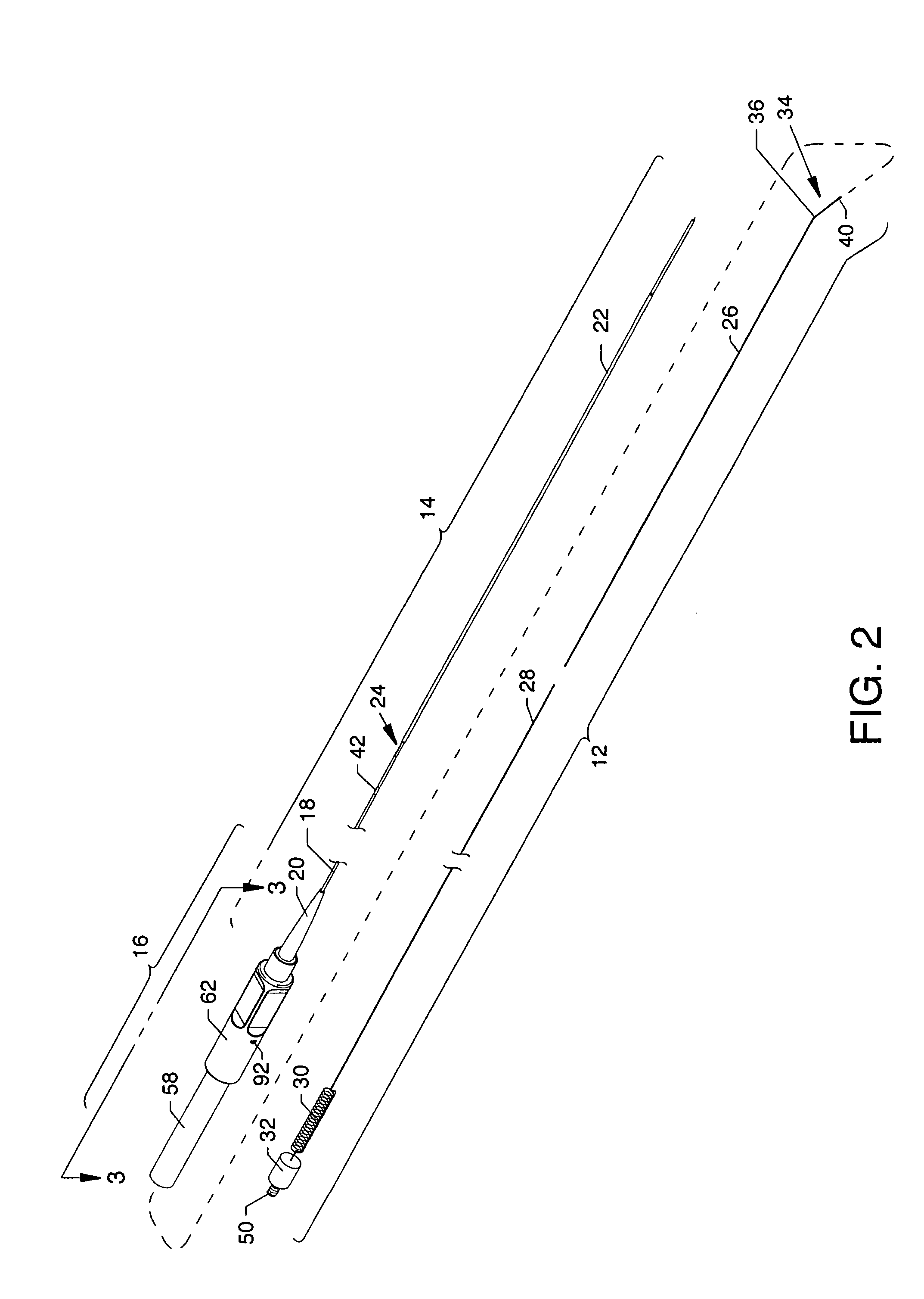
[0038]FIG. 1 is an isometric view of a forwardly directable fluid jet crossing catheter 10 of the present invention, and FIG. 2 is an expanded view of FIG. 1 showing a jet body 12 removed from and exterior to a flexible catheter tube 14. The proximal end of the flexible catheter tube 14 and the proximal end of the jet body 12 align and secure within an operating handle 16 located at the proximal end of the forwardly directable fluid jet crossing catheter 10. The flexible catheter tube 14 includes a flexible coated tube 18 extending distally from a flexible strain relief 20 located at one end of the operating handle 16 and also includes a sheath 22 being slightly larger in diameter than the flexible coated tube 18 where the proximal end of the sheath 22 is aligned over and about the smaller distal end of the flexible coated tube 18 at a guidewire tube exit region 24. The configuration of the guidewire tube exit region 24 is closely related to and described in patent application Ser. ...


PUM


Abstract

A forwardly directable fluid jet crossing catheter having a positionable jet body which can be longitudinally and rotationally positioned in order to direct a fluid jet stream to impinge, break through, and cross a chronic total occlusion. The distal end of the catheter includes a tip of super-elastic material having a flexible bend aligned within the distal portion of a sheath which tip is directable in response to the longitudinal and rotational orientation of a positionable jet body, whereby a fluid jet stream can be controlled in angular and rotational directions.

Description

CROSS REFERENCES TO RELATED APPLICATIONS[0001]This application claims priority from the earlier filed U.S. Provisional Application No. 60 / 936,507 filed Jun. 20, 2007, entitled “Forwardly Directable Fluid Jet Crossing Catheter”, and is hereby incorporated into this application by reference as if fully set forth herein.BACKGROUND OF THE INVENTION[0002]1. Field of the Invention[0003]The present invention relates to the field of catheters, and more particularly, relates to a forwardly directable fluid jet crossing catheter used for the purpose of crossing a Chronic Total Occlusion (CTO), whereby a moderate speed and safe velocity fluid jet is used to wear away arterial lesions forming a CTO and advancing therethrough. Chronic total occlusions are arterial lesions that have progressed to the point where there is no flow through the vessel (total occlusion). Furthermore, it is generally considered highly difficult to cross a CTO with a standard support guidewire. In other words, if a tota...

Claims


Application Information

Patent Timeline
IPC IPC(8): A61M25/085
CPCA61B17/32037A61B2017/003A61B2017/00331A61B2017/00867A61B2017/22094
Inventor BONNETTE, MICHAEL J.THOR, ERIC J.MORRIS, DAVID B.KOZAK, DEBRA M.
Owner MEDRAD INC.
Why Eureka
Try Eureka