Sutureless vessel anastomosis method and apparatus

a technology of sutureless vessels and anastomosis methods, applied in the field of sutureless vessel anastomosis methods and apparatus, can solve the problems of failure and patency rate of procedure, laser or other heating devices, and the inability to achieve the anastomosis of small vessels, so as to improve the adherence of the vessel

Inactive Publication Date: 2008-12-25
UNIV GENT
View PDF13 Cites 6 Cited by
  • Summary
  • Abstract
  • Description
  • Claims
  • Application Information

AI Technical Summary

Benefits of technology

[0008]Embodiments of the present invention provide improved apparatus and methods for anastomoses of hollow organs such as blood and other vessels. A method according to one embodiment of the present invention is for end-to-end vessel anastomosis. A vessel support is provided that includes a vessel receiving portion and a handle portion extending therefrom. The vessel-receiving portion comprises an interrupted annulus having an inner diameter and an outer diameter. The handle portion is removable from the vessel-receiving portion. The vessel-receiving portion of the vessel support is positioned around the end of a first vessel such that the end of the first vessel is disposed through the inner diameter of the vessel-receiving portion. The end of the first vessel is everted around the outer diameter of the annulus of the vessel-receiving portion such that an inner surface of the vessel is directed outwardly. The end of a second vessel is positioned over the inverted end of the first vessel such

Problems solved by technology

A disadvantage to using sutures for anastomosis is that the success and patency rate of the procedure is directly related to the skills and dexterity of the surgeon.
Anastomosis of small vessels is both difficult and time consuming.
The procedure illustrated in FIGS. 1A-1C also has the disadvantage that it introduces a foreign material, the suture, into the blood vessel, which may eventually lead to thrombos

Method used


Image

  • Sutureless vessel anastomosis method and apparatus
  • Sutureless vessel anastomosis method and apparatus
  • Sutureless vessel anastomosis method and apparatus

Examples


Embodiment Construction

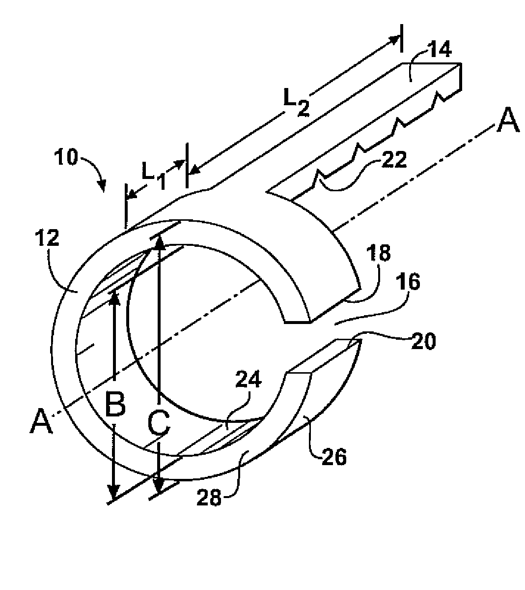
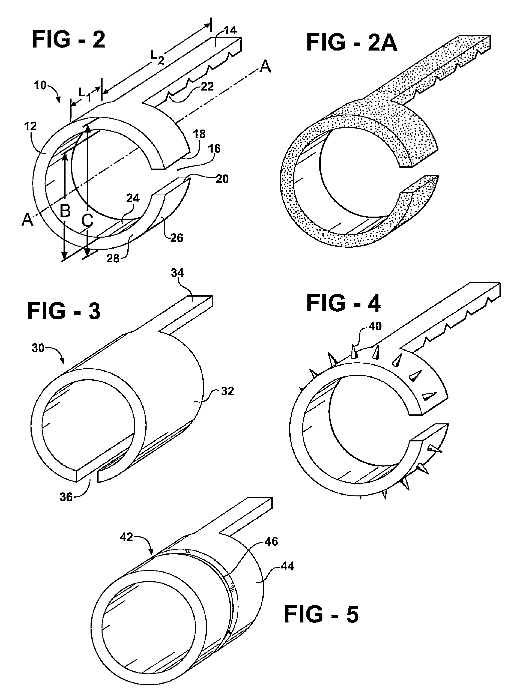
[0024]The present invention provides embodiments of apparatus and methods for performing anastomosis of hollow organs such as blood vessels. FIG. 2 illustrates a first embodiment of a blood vessel support 10 according to the present invention. The blood vessel support includes a vessel receiving portion 12 and a handle portion 14 extending therefrom. The vessel-receiving portion 12 may be said to be generally annular or formed as an annulus around an axis A-A. The vessel-receiving portion 12 may be generally cylindrical and extend along the axis A-A or may be shorter and more ringlike. It is preferred that the inner diameter B is generally constant along the longitudinal length L1 of the generally annular vessel-receiving portion 12. The vessel-receiving portion 12 may also be said to have an outer diameter C that is also preferably generally constant along the longitudinal length L1 of the vessel-receiving portion 12. As shown, the vessel-receiving portion 12 is an interrupted annu...


PUM


Abstract

A method for performing end-to-end vessel anastomosis includes providing a vessel support including a vessel receiving portion and a handle portion extending therefrom. The vessel receiving portion is an annulus. The vessel receiving portion is positioned around the end of a first vessel and the end of the first vessel is everted about the outer diameter of the vessel receiving portion such that the inner surface of the vessel is directed outwardly. The end of the second vessel is positioned over the everted end of the first vessel such that the inner surface of the second vessel is disposed against the inner surface of the first vessel. A surgical adhesive is provided and is used to adhere the ends of the vessels together without requiring the application of heat or radiant energy. The handle portion of the vessel support may be removed.

Description

FIELD OF THE INVENTION[0001]The present invention relates generally to methods and apparatus for performing anastomoses of hollow organs such as blood vessels.BACKGROUND OF THE INVENTION[0002]Many surgical procedures require attachment of hollow organs to each other, generally referred to as anastomosis. Most often, this procedure is required with blood vessels, referred to as vessel anastomosis. FIGS. 1A-1C illustrate a typical procedure for end-to-end anastomosis of a pair of blood vessels. The vessels are butted end-to-end and stitched together with small separate or running sutures. This approach to surgical interconnection may be used with both large and small vessels, with the number and size of sutures depending on the size of the vessel. A disadvantage to using sutures for anastomosis is that the success and patency rate of the procedure is directly related to the skills and dexterity of the surgeon. Anastomosis of small vessels is both difficult and time consuming.[0003]The...

Claims


Application Information

Patent Timeline
IPC IPC(8): A61B17/11
CPCA61B17/11A61B17/1114A61B2017/00004A61B2017/1107A61B2017/1132
Inventor BLONDEEL, PHILLIP N.
Owner UNIV GENT
Why Eureka
Try Eureka