
Medical Device Access Control Apparatus and Method

Inactive Publication Date: 2008-12-25
BARBOUR MICHAEL M MR +1
View PDF18 Cites 20 Cited by
  • Summary
  • Abstract
  • Description
  • Claims
  • Application Information

AI Technical Summary

Benefits of technology

[0008]In one embodiment, the invention includes a control apparatus coupled to a medical device including a treatment portion. The apparatus may include a removable media reader configured to read information from a removable media and transmit the information to a processor and to receive information from the processor and write the information to the removable media, a power supply, and a power control unit coupled to the medical device and the power supply where the power control unit is configured to provide power to the medical device upon receiving an activation signal and is arranged such that the treatment portion of the medical device does not receive power except through the power control unit. The apparatus may also include a processor c

Problems solved by technology

Each of the above-mentioned devices are considered to be capital equipment often costing several thousands of dollars.
Thus, to purchase a single piece of equipment, a physician or other practitioner must raise a large amount of capital before ever treating a patient with the equipment.
This often proves difficult and limits the amount of equipment that a practitioner can obtain.
This capital equipment model also presents drawbacks to the medical device manufacturer.
As discussed above, many practitioners are unable to purchase equipment because they lack the upfront capital, and thus the market for the devices is reduced.
Additionally, while the manufacturer receives a large upfront sum for each piece of equipment sold, the manufacturer has no way to capture a continuing revenue stream.
As a medical device saturates the market, this drawback becomes more acute as new sales decrease.
Finally, while manufacturers or distributors have instituted programs where a medical device is leased for a number of years, such a program requires significant overhead to administer.
This simple, hard-wired design presents difficulties in adding more advanced features to the device such as, for example, access control features, without completely redesigning the device.
Such a complete redesign may be undesirable for several reasons including the costs and time to re-engineer, test, and fabricate a new product.

Method used


Image

  • Medical Device Access Control Apparatus and Method
  • Medical Device Access Control Apparatus and Method
  • Medical Device Access Control Apparatus and Method

Examples


Embodiment Construction

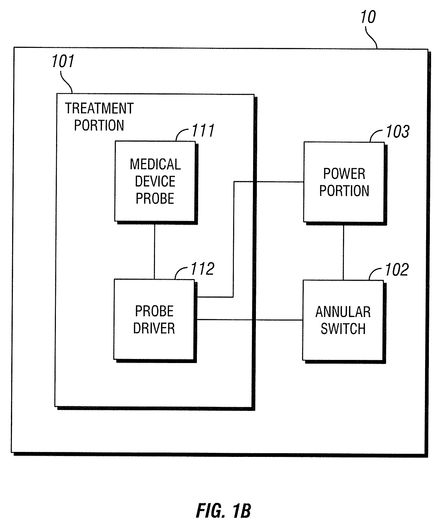
[0019]A block diagram of prior art medical device 10 is shown in FIG. 1B. While reference is made to medical device 10, medical device 10 is simply used in an exemplary manner. It will be understood by those skilled in the art that the methods and configurations discussed below may be adapted for use with various medical devices. Treatment portion 101 includes medical device probe 111 and probe driver 112. Medical device probe 111 consists of the actual electromagnetic excitation hardware. In medical device 10, the excitation may be provided by multiple GaAlAs laser diodes. Probe driver 112 includes circuitry to regulate the power supplied to medical device probe 111 thus regulating excitation of the probe. In medical device 10, this circuitry is relatively simple. The circuitry, responsive to a signal from annular switch 102, provides a set amount of power from power portion 103 to medical device probe 111 for a set period of time. This functionality may be implemented using basic ...


PUM


Abstract

A method and apparatus for providing access control to a medical device. A control device may be attached to the medical device to regulate power flow to the medical device and monitor usage of the device. The control device may accept removable media and read information from the media. The information may indicate control devices with which the removable media is designated to work, as well as an amount of authorization credit. The control device, after confirming that the removable media authorized to work with that control device and that it includes sufficient authorization credit, may provide power to the medical device. The control device may then monitor the medical device and when use of the medical device is detected, the control device may write new information to the removable media decreasing the amount of authorization credit. In a preferred embodiment, the removable media is an RFID memory card.

Description

TECHNICAL FIELD[0001]The following relates generally to medical devices and more specifically to controlled access to a medical device.BACKGROUND OF THE INVENTION[0002]Medical devices utilizing electromagnetic energy to diagnose or treat physiological symptoms have become common tools used by physicians and physical therapists in patient treatment. Such devices used for diagnostic purposes include x-ray machines, CT scanners, and MRI machines. Devices used for treatment purposes include Electromagnetic Field Therapy (EMFT) equipment used in treatment of soft tissue, Extracorporeal Shock Wave Lithotripsy (ESWL) equipment used to break up stones that form in the kidney, bladder, ureters, or gallbladder, Low-Level Laser Therapy (LLLT) equipment used to treat various conditions including Carpal Tunnel Syndrome, and the like.[0003]An exemplary LLLT device is described in commonly-assigned U.S. Pat. No. 5,464,436 to Smith, which is hereby incorporated by reference in its entirety. A comme...

Claims


Application Information

Patent Timeline
IPC IPC(8): A61N1/02
CPCA61N1/37235A61N1/3787
Inventor SIMPSON, FRED A.TEPPER, JOHN
Owner BARBOUR MICHAEL M MR
Features
  • Generate Ideas
  • Intellectual Property
  • Life Sciences
  • Materials
  • Tech Scout
  • Unparalleled Data Quality
  • Higher Quality Content
  • 60% Fewer Hallucinations
Learn More