DMA transfer apparatus

a transfer apparatus and dma technology, applied in the field of dma transfer apparatus, can solve the problems of unduly long occupied bus bandwidth and lower the performance of the entire system, and achieve the effect of reducing the ratio of occupied bus bandwidth by low-speed peripheral hardware, improving system performance, and reducing the occupied bus bandwidth

Inactive Publication Date: 2008-12-25
PANASONIC CORP
View PDF6 Cites 6 Cited by
  • Summary
  • Abstract
  • Description
  • Claims
  • Application Information

AI Technical Summary

Benefits of technology

[0018]This configuration makes it possible to avoid a FIFO overflow and to minimize the bus occupation time because a mechanism of automatically selecting access of an optimum burst length on the basis of the number of stages of data stacked in the FIFO is provided.
[0020]This configuration makes it possible to avoid a FIFO underflow and to minimize the bus occupation time because a mechanism of automatically selecting access of an optimum burst length on the basis of the number of stages of data stacked in the FIFO is provided.
[0022]This configuration makes it possible to always perform a DMA transfer with a usable longest burst length without causing a FIFO overflow or underflow and hence to minimize the bus occupation time.
[0023]According to the invention, a burst transfer is enabled in a DMA transfer to or from a FIFO, whereby a high-speed DMA transfer is realized which uses a burst transfer to or from low-speed peripheral hardware having a FIFO. As a result, the ratio of occupation of a bus bandwidth by the low-speed peripheral hardware can be reduced and the performance of the entire system can be increased.

Problems solved by technology

Therefore, it is necessary to repeat a single transfer to or from the peripheral hardware having the FIFO, as a result of which the bus bandwidth is occupied for an unduly long time for the low-speed peripheral hardware.
A problem arises that this affects a data transfer to or from another piece of, high-speed peripheral hardware that also needs the bus bandwidth and thereby lowers the performance of the entire system.

Method used


Image

  • DMA transfer apparatus
  • DMA transfer apparatus
  • DMA transfer apparatus

Examples


Embodiment Construction

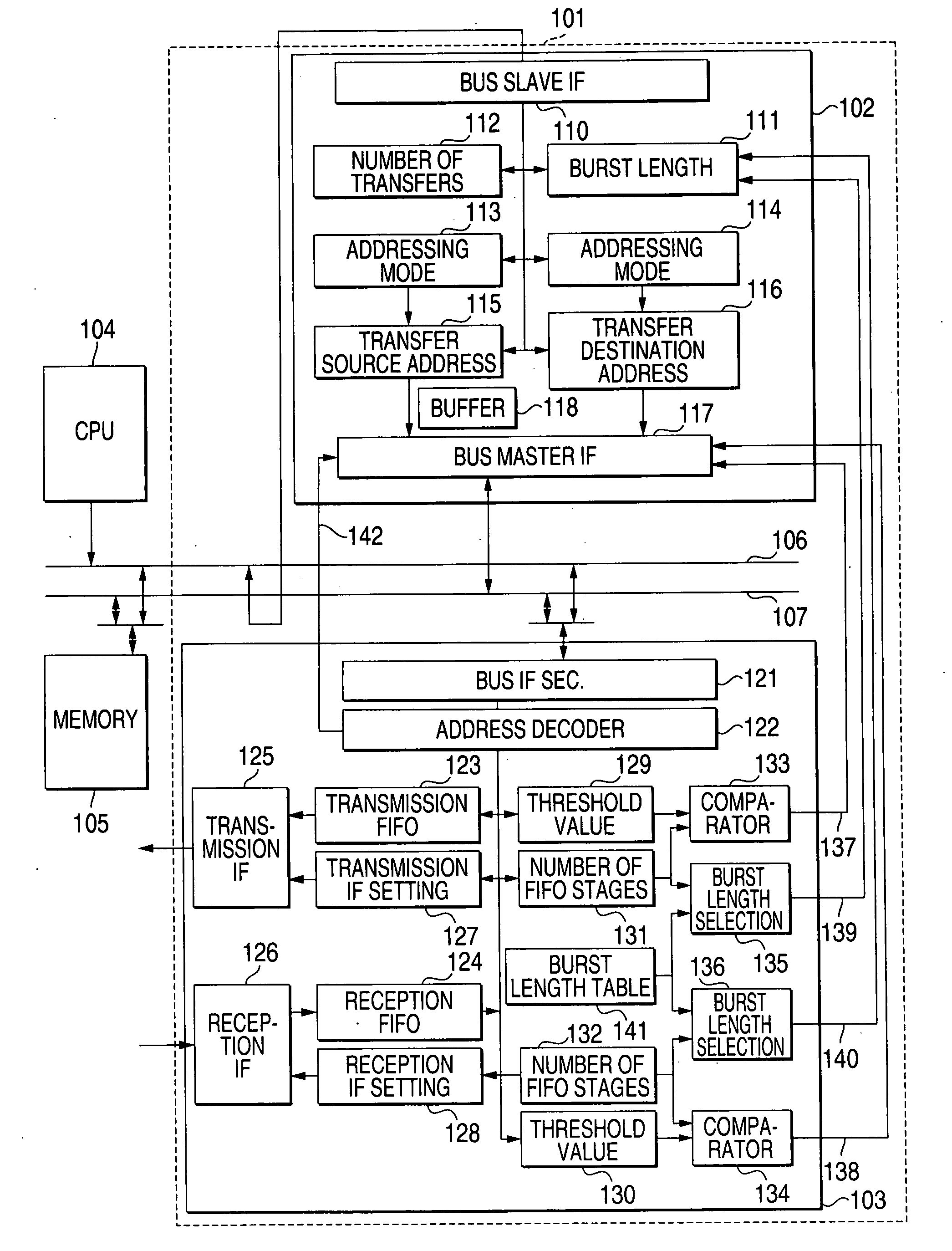
[0033]FIG. 1 is a block chart showing the configuration of a DMA transfer apparatus according to an embodiment of the present invention. In FIG. 1, reference numeral 101 denotes a DMA transfer apparatus according to the invention; 104, a CPU; 105, a memory; 106, a CPU bus having the CPU 104 as a bus master; and 107, a DMA bus capable of not only a single transfer but also two-time, four-time, eight-time, and 16-time burst transfers. Other various kinds of hardware that are connected for various uses of the system are not shown in FIG. 1.

[0034]In the DMA transfer apparatus 101, reference numeral 102 denotes a DMA control block which has CPU-104-settable control registers 111-116 and a bus master interface 117 and serves as a bus master of the DMA bus 107. Reference numeral 103 denotes a FIFO-incorporated block which is equipped with communication interface for data communication with external devices and FIFOs as buffer memories.

[0035]A bus arbitration circuit allows access to the FI...


PUM


Abstract

A DMA transfer apparatus 101 is equipped with a DMA control block 102 and a FIFO-incorporated block 103. The DMA control block 102 is connected, as a bus master, to a DMA bus capable of burst transfer and having a function of controlling a burst transfer by generating burst access for sending data consecutively a certain number of times while incrementing the address after sending a command. The FIFO-incorporated block 103 is connected the DMA bus as its slave and having a FIFO whose address is mapped to a continuous address space. An arrangement is provided so that a parameter dedicated to FIFO transfer can be set in an addressing mode setting register of a control register group of the DMA control block 102, whereby a burst transfer to or from the FIFO whose address is mapped to the continuous address space is controlled.

Description

BACKGROUND OF THE INVENTION[0001]1. Field of the Invention[0002]The present invention relates to a DMA transfer apparatus and, more particularly, to a technique for enabling a burst transfer in a DMA transfer apparatus that is equipped with an input / output interface for connection of low-speed peripheral hardware and a FIFO as a buffer memory.[0003]2. Description of the Related Art[0004]In conventional computer systems including a CPU and high-speed peripheral hardware, data are transferred directly between a memory and the high-speed peripheral hardware by using a DMA transfer apparatus, whereby the processing load of the CPU is reduced.[0005]There are computer systems which perform a DMA transfer and have a burst transfer function of sending an address once in synchronism with a clock signal and then transferring data consecutively a certain number of times while incrementing the address. A high-speed data transfer between the memory and the high-speed peripheral hardware is thus ...

Claims


Application Information

Patent Timeline
Patent Type & Authority Applications(United States)
IPC IPC(8): G06F13/28
CPCG06F13/28
Inventor SHIRASAKI, MOTOYASUTSUKAMOTO, AKIHITO
Owner PANASONIC CORP
Why Eureka
Try Eureka