Hinge Device and Electronic Device Using Hinge Device

Inactive Publication Date: 2009-01-01
STRAWBERRY
View PDF5 Cites 111 Cited by
  • Summary
  • Abstract
  • Description
  • Claims
  • Application Information

AI Technical Summary

Benefits of technology

[0027]Because the present invention is configured as described above, an innovative hinge device and an electronic device that uses the hinge device are provided whereby a second member can pivot open in undulating fashion with respect to a first member from a state in which the first member and the second member are mutually overlapped; the hinge device can pivotally attach both members and be accommodated between both members so that a protruding part or a stepped part does not occur in the middle even when the open surfaces of the members are straight open or at a right angle when the members are pivoted open; the members can be pivoted closed into a mutually overlapped state while being configured so as also to form a flat open surface as previously described when the members are pivoted open, due to the dual-shaft structure being disposed between the members; and even though a dual-shaft structure is employed, co-pivoting is created by a connecting link part bridged between pivoting parts that move in conjunction with the pivoting of each member, whereby the pivoting of each shaft is restricted, the pivoting of both members is substantially synchronized, and the members can smoothly pivot to the desired angle without wobbling.
[0028]In the present invention, since the synchronization of the shafts by co-pivoting is accomplished by a link system using the connecting link part for bridging between the pivoting parts of the shafts rather than by a gear system (there are, however, cases in which complete synchronization is not achieved, as in a gear system), an even more superior and innovative hinge device and electronic device that uses the hinge device are obtained in which the drawbacks of the aforementioned gear system are overcome, there is a degree of freedom in the inter-shaft pitch and the amount of occupied space, the cos

Problems solved by technology

However, since each of the two shafts pivots without restriction, as shown in FIG. 13

Method used


Image

  • Hinge Device and Electronic Device Using Hinge Device
  • Hinge Device and Electronic Device Using Hinge Device
  • Hinge Device and Electronic Device Using Hinge Device

Examples


Embodiment Construction

[0049]Preferred embodiments (the manner in which the present invention is implemented) of the present invention are briefly described below with reference to the diagrams while indicating the effects of the present invention.

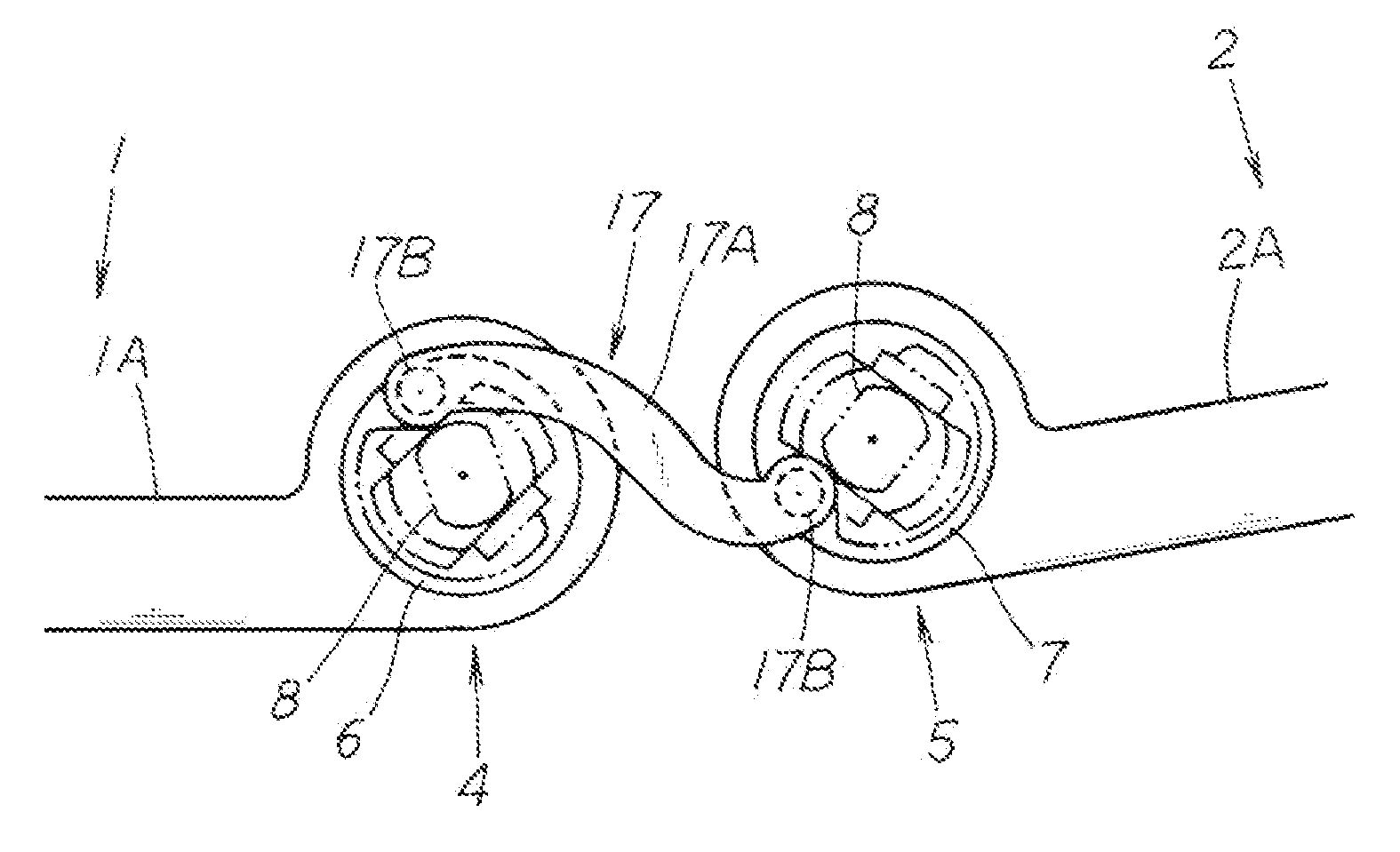
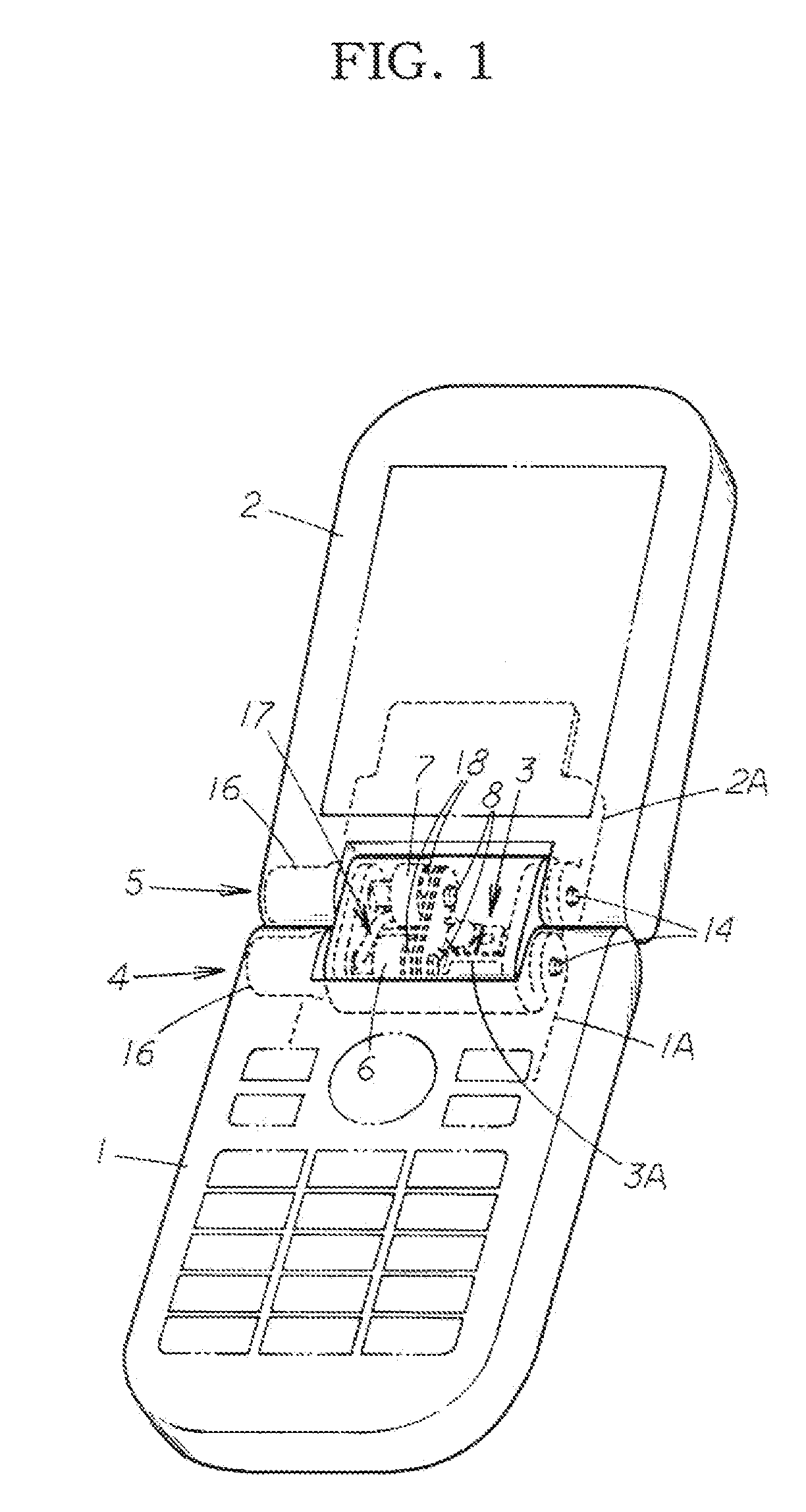
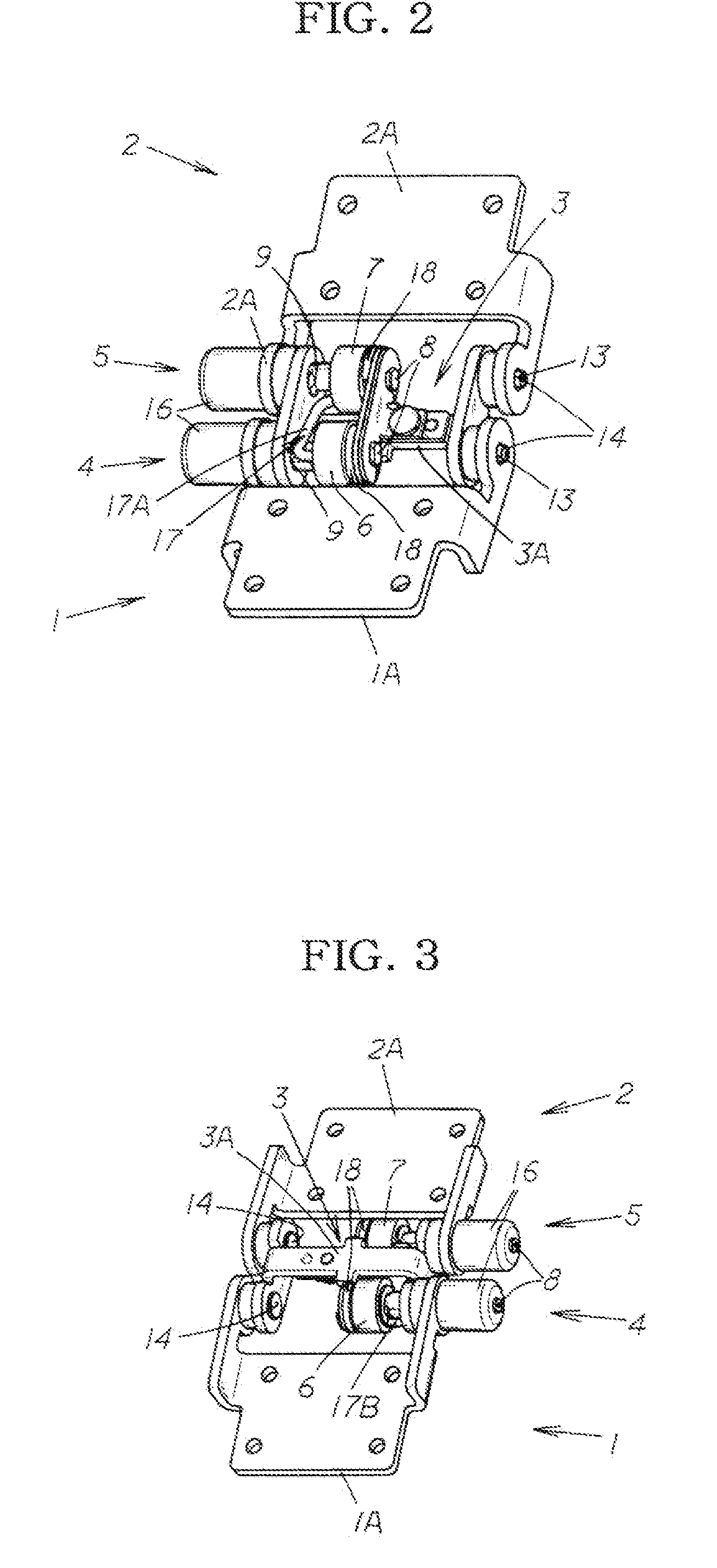
[0050]A hinge base 3 is disposed between a first member 1 and a second member 2. The end part of the first member 1 and the hinge base 3 are pivotably connected via a first pivot shaft part 4, and the hinge base 3 and the end part of the second member 2 are pivotably connected via a second pivot shaft part 5. The first member 1 is disposed on the intermediate part of the hinge base 3 via the first pivot shaft part 4 so that the first member 1 is free to perform an undulating pivoting motion, and the second member 2 is disposed on the hinge base 3 via the second pivot shaft part 5 so that the second member 2 is free to perform an undulating pivoting motion.

[0051]Accordingly, the second member 2 is free to perform an undulating pivoting motion with respect to the ...


PUM


Abstract

It is an object of the present invention to provide an innovative hinge device of a dual-shaft construction that performs a synchronized pivoting motion, and that can smoothly perform an undulating pivoting motion without any unsteadiness; and an electronic device using the hinge device. The present invention is a hinge device in which a second member 2 is connected to a first member 1 so that the second member 2 can perform an undulating pivoting motion from a state in which the first member 1 and second member 2 are overlapped, wherein the hinge device is constructed so that pivot shaft parts 4 and 5 are disposed in parallel on a hinge base 3 disposed between the end part of the first member 1 and the end part of the second member 2; the hinge base 3 is provided so as to be free to perform an undulating pivoting motion with respect to the first member 1 via the first pivot shaft part 4; the second member 2 is disposed so as to be free to perform an undulating pivoting motion with respect to the hinge base 3 via the second pivot shaft part 5; a first pivoting part 6 and second pivoting part 7 that pivot in a relative manner when performing an undulating pivoting motion are respectively disposed on the first pivot shaft part 4 and second pivot shaft part 5; and the first pivoting part 6 and second pivoting part 7 are connected by a connecting link part 17, so that the second pivoting part 7 is caused to perform a transmitted co-pivoting motion by this first pivoting part 6.

Description

CROSS REFERENCE TO RELATED APPLICATIONS[0001]This application is a national phase of PCT / JP2007 / 050504, filed on Jan. 16, 2007, which claims priority to JP 2006-014634, filed on Jan. 24, 2006, the entire contents of which are incorporated herein by reference in their entireties.TECHNICAL FIELD[0002]The present invention relates to a hinge device provided to the pivot mounting part of a mobile telephone, a mobile device, a notebook personal computer, a digital camera, or other electronic device, for example, and to an electronic device that uses the hinge device.BACKGROUND ART[0003]When a configuration is adopted in which the end parts of two members are connected to each other by a hinge device so that one member is able to pivot with respect to the other member, merely providing the hinge device flush with one member and connecting the other member via the hinge device does not enable both members to be overlapped on each other even by pivoting one member with respect to the other ...

Claims


Application Information

Patent Timeline
IPC IPC(8): E05D3/06F16C11/04F16C11/10H04M1/02
CPCG06F1/1616Y10T16/547H04M1/022G06F1/1681H04B1/38F16C11/10
Inventor YAMANAMI, MASAHIKO
Owner STRAWBERRY
Why Eureka
Try Eureka