Method of and an Apparatus for Drying Solid Materials and Mixtures of Solid Materials

a technology of solid materials and apparatuses, which is applied in the direction of drying solid materials, drying machines, lighting and heating apparatus, etc., can solve the problems of long retention time, inability to at least substantially allow the material to be dried to flow to the gas volume between the wall surfaces, and large size of the dryer

Inactive Publication Date: 2009-01-01
BERG EERO
View PDF3 Cites 8 Cited by
  • Summary
  • Abstract
  • Description
  • Claims
  • Application Information

AI Technical Summary

Benefits of technology

[0031]In one preferred embodiment in accordance with the present invention every other wall element is first vertically moved upwards during the emptying stage. After a short while, the rest of the wall elements are moved in the same way, in other words upwards. It is, of course, possible, if so desired, to move wall elements at the same time, for example, to different directions. It is possible to move wall elements several times relative to each other during each emptying stage. The movements of the wall elements are chosen so as to bring about the necessary movement of material particles relative to the wall surfaces and to each other to promote the emptying of the drying passage.

Problems solved by technology

Drying at low temperatures requires a longer retention time in the dryer for the material to be dried, whereby the size of the dryer easily increases very much.
The wall surfaces are provided with openings, which have a size and shape allowing the gas flow either from the gas volume to the drying passage or from the drying passage to the gas volume, but which do not at least substantially allow the material to be dried to flow to the gas volume between the wall surfaces.
The emptying of the dried material merely by means of gravity is, however, often difficult to control.
Part of the material easily sticks to the walls of the drying passage and “arches”, whereby the flowing of the material downwards is slow and incomplete.

Method used


Image

  • Method of and an Apparatus for Drying Solid Materials and Mixtures of Solid Materials
  • Method of and an Apparatus for Drying Solid Materials and Mixtures of Solid Materials
  • Method of and an Apparatus for Drying Solid Materials and Mixtures of Solid Materials

Examples


Embodiment Construction

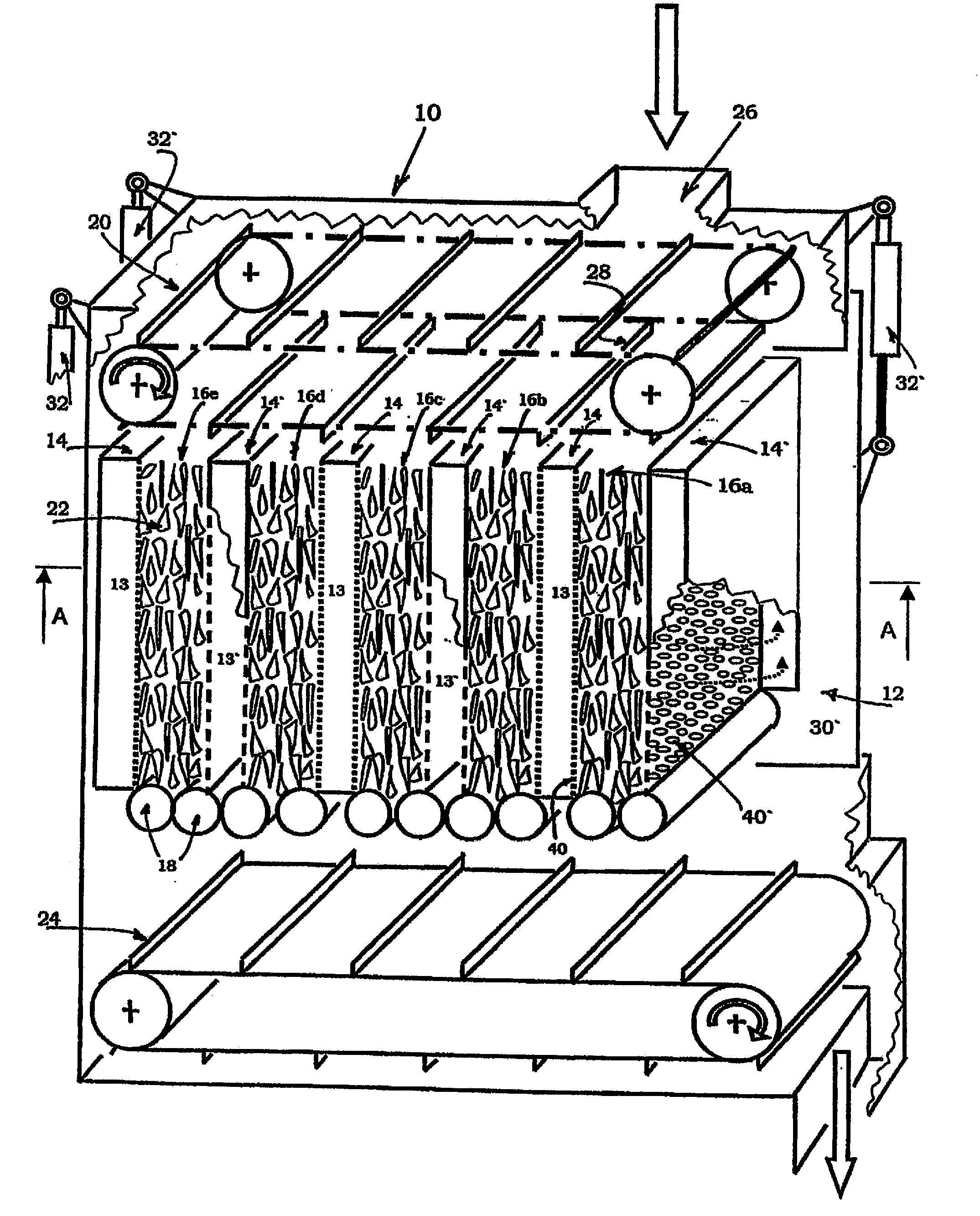
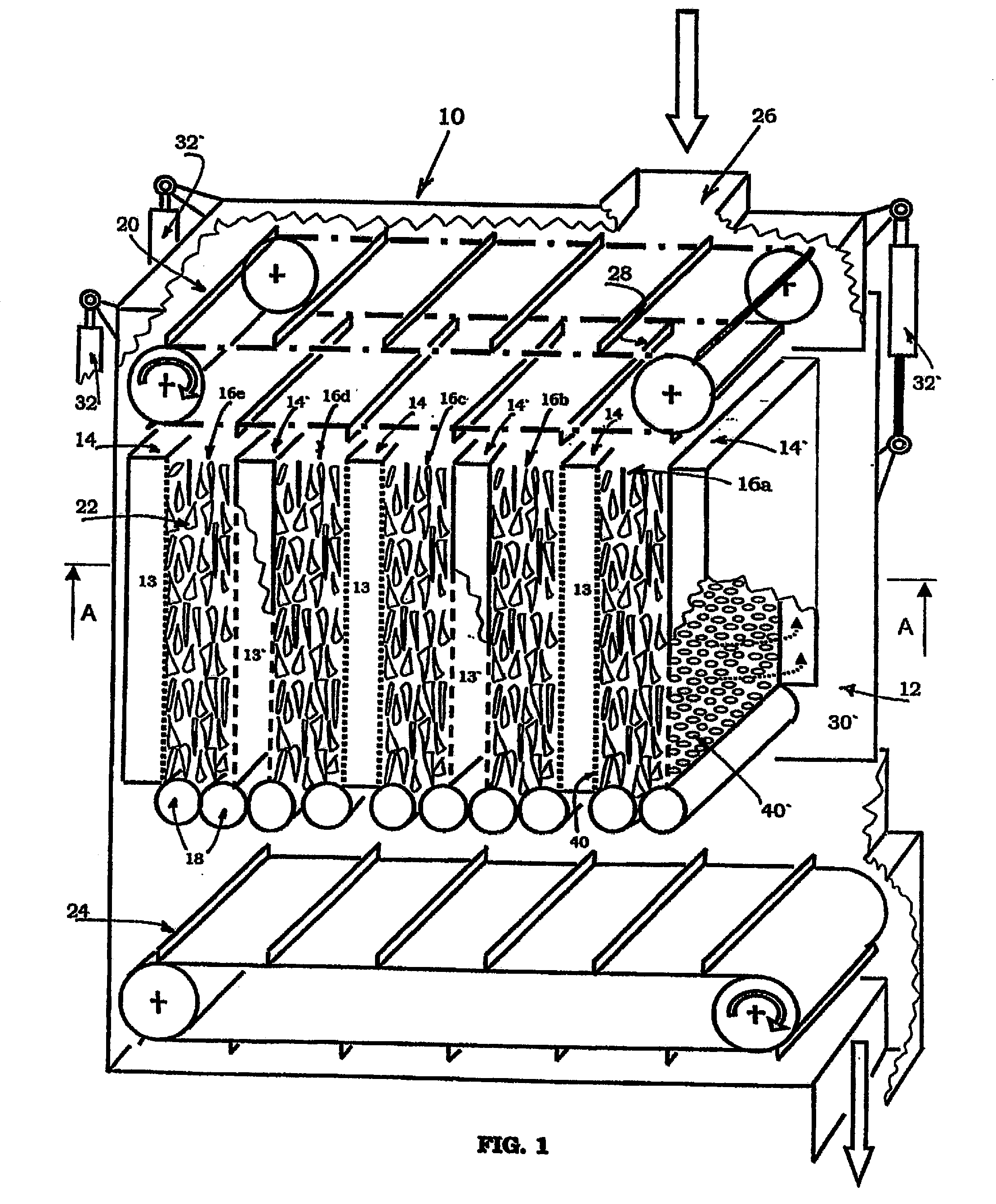
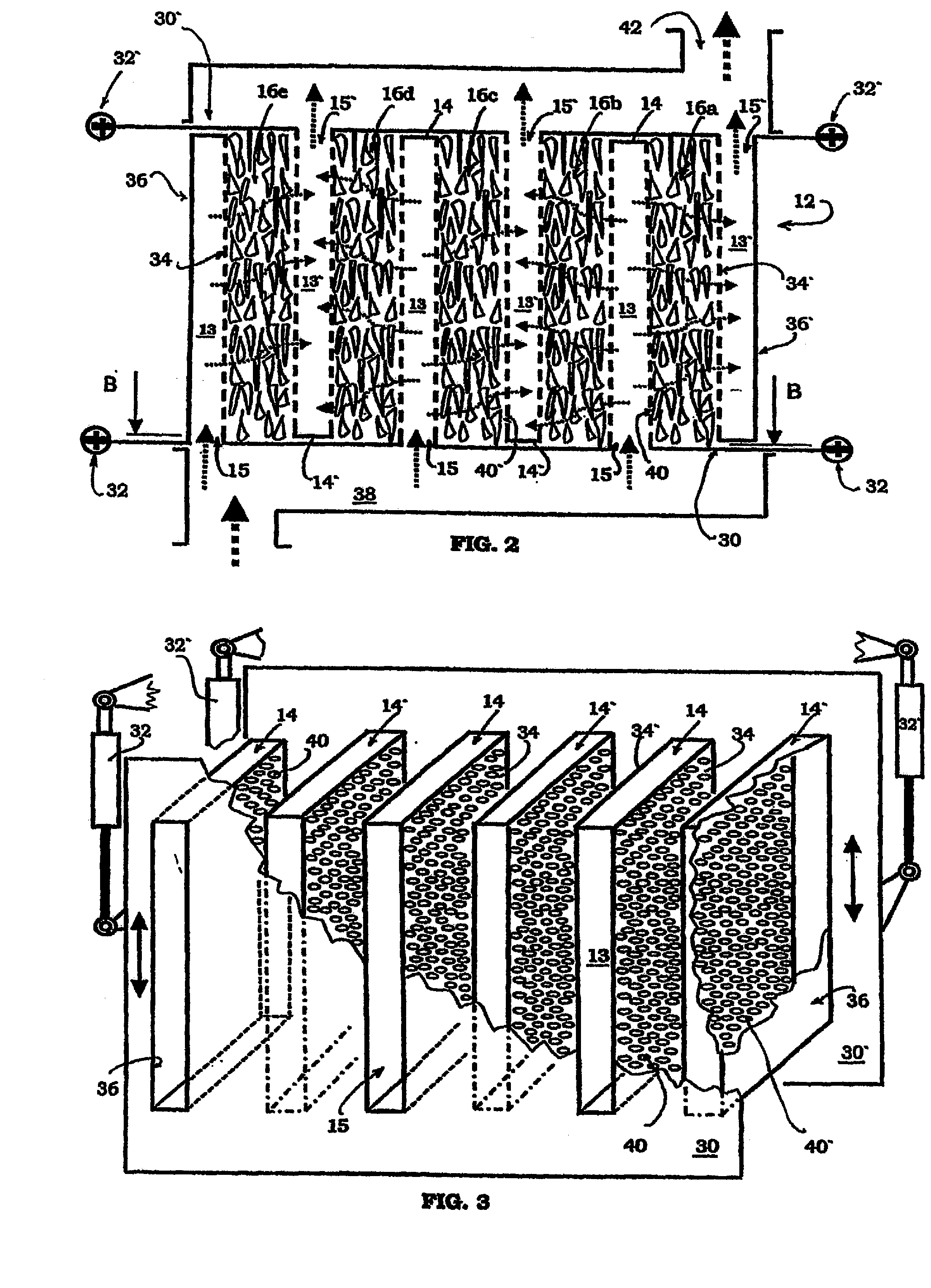
[0051]FIGS. 1 and 2 illustrate a drying apparatus, in other words a dryer 10 for solid materials in accordance with the invention. A dryer can be arranged in a heat-insulated box or like. The dryer comprises a drying space 12, to which a number of vertical, from inside open wall elements 14 and 14′ is arranged. The wall elements are positioned adjacently in such a way that they divide the drying space into vertical drying sections or drying passages 16a-16e.

[0052]The drying passages 16a-16e are open from above. The bottom openings at the bottom of the passages can be closed. Closing means 18 in FIG. 1 are in closed-position, whereby the material to be dried is not allowed to flow away through the bottom opening of the drying passage. There are two closing means 18 in the disclosed exemplary embodiment in connection with each drying passage. The closing means are attached to the lower edge of the wall elements limiting the passage. The closing means disclosed in the figure are infla...


PUM


Abstract

A method of and an apparatus for drying solid materials and material mixtures in a dryer, comprising a drying space, which is divided by wall elements into drying passages in such a way that each drying passage is limited into two wall elements. Material to be dried is supplied to the drying passages through the upper part thereof. Drying gas is supplied to the drying passages through a first wall element limiting them and moist drying gas is led out of the drying passage to a second wall element limiting them. The dried material is discharged from the drying passages through the lower part thereof. Adjacent wall elements are moved relative to each other in connection with the emptying of the drying passages.

Description

CROSS REFERENCE TO RELATED APPLICATIONS[0001]This application is a Section 371 filing of International Application No. PCT / FI2005 / 000418 filed on Sep. 30, 2005, and published as WO 2006 / 037840 on Apr. 13, 2006, which claims priority from Finnish Application No. FI20041309 filed on Oct. 8, 2004. These applications are hereby incorporated by reference in their entirety.TECHNICAL FIELD[0002]The present invention relates to a method of and an apparatus for drying solid materials and mixtures of solid materials defined by the preambles of the independent claims disclosed below.BACKGROUND AND SUMMARY OF ASPECTS OF THE INVENTION[0003]Many solid fuels, such as especially biofuels, must be dried before their actual usage as fuel. Biofuels are typically dried with hot gas in drum dryers or fluidized bed dryers. Drying takes place in these apparatuses at a relatively high temperature, typically at 175 to 500° C. For example, hot flue gases or fired steam is thereby used as drying gas. To produ...

Claims


Application Information

Patent Timeline
Patent Type & Authority Applications(United States)
IPC IPC(8): F26B19/00F26BF26B17/12F26B25/00
CPCF26B25/002F26B17/122
Inventor BERG, EERO
Owner BERG EERO
Why Eureka
Try Eureka