

Wind energy plant tower
- Summary
- Abstract
- Description
- Claims
- Application Information
AI Technical Summary
Benefits of technology
Problems solved by technology
Method used
Image

Examples
Embodiment Construction
[0037]While this invention may be embodied in many different forms, there are described in detail herein a specific preferred embodiment of the invention. This description is an exemplification of the principles of the invention and is not intended to limit the invention to the particular embodiment illustrated
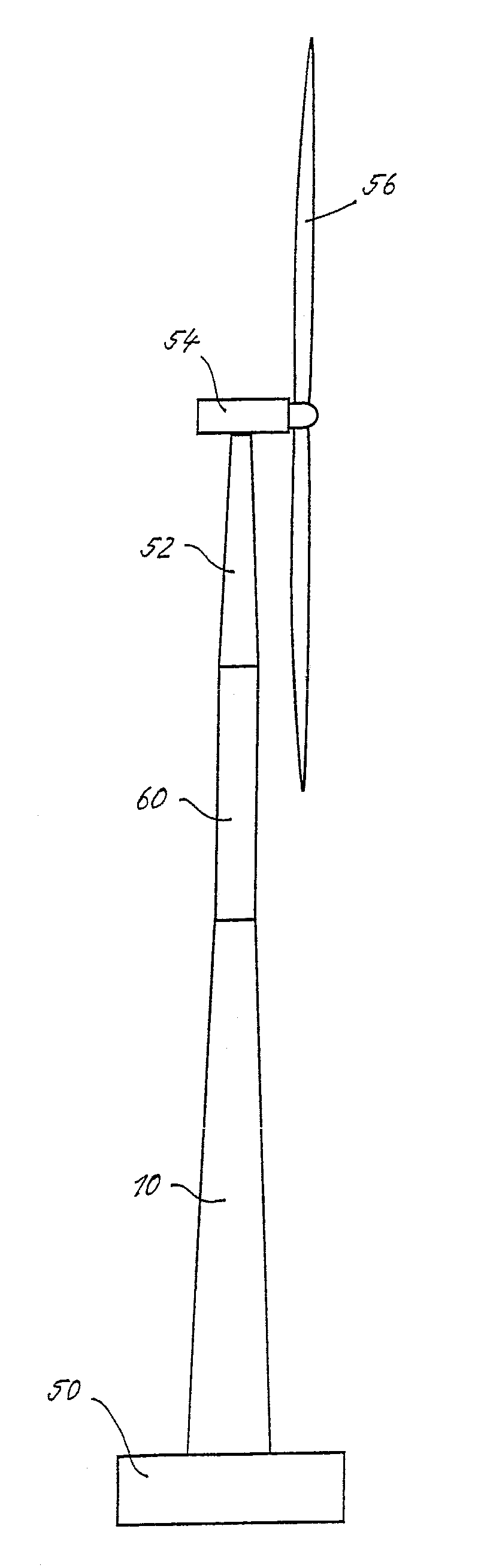
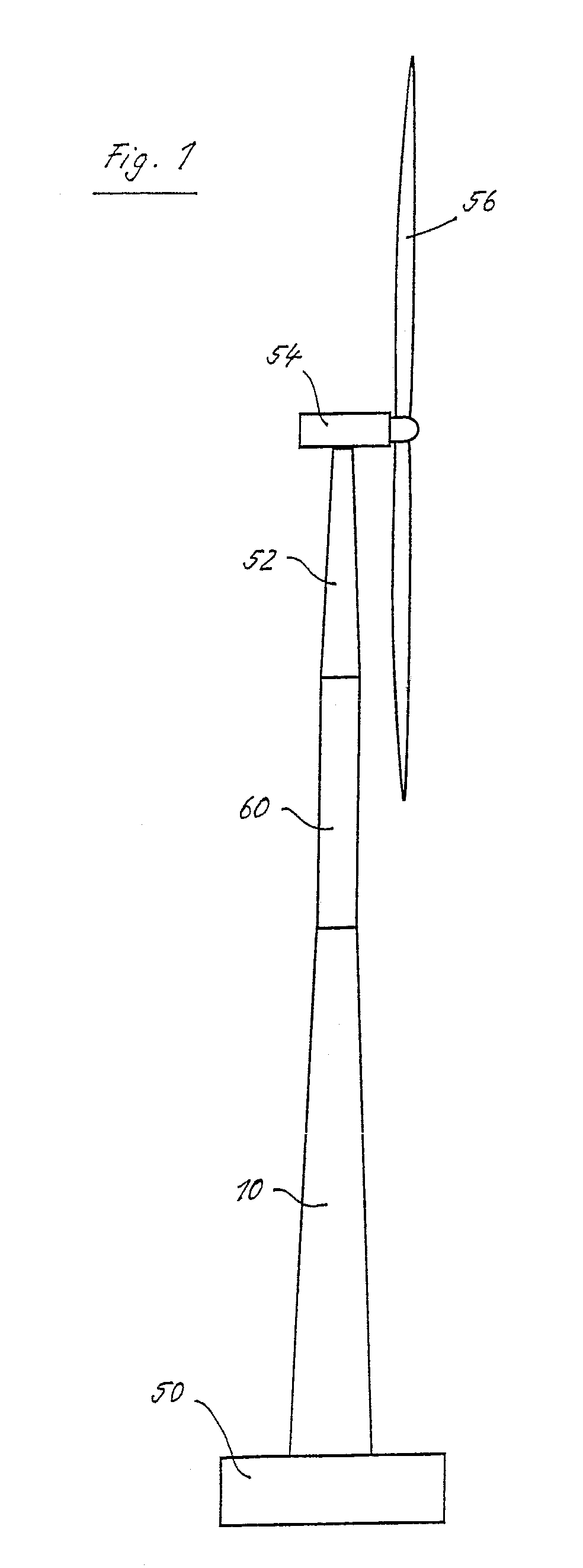
[0038]The wind energy plant depicted in FIG. 1 has a tower portion 10 made of ferroconcrete, which rests on a concrete foundation 50. Above the tower portion 10, there is a tubular steel-made tower segment 60, which is shaped circular cylindrical. A further steel-made tower segment 52 is conical and arranged above the tower segment 60. On its upper end, it has a bearing for the nacelle 54 of the wind energy plant. A rotor 56 with plural rotor blades is rotatably mounted on the nacelle 54. It drives a generator for providing electric power.
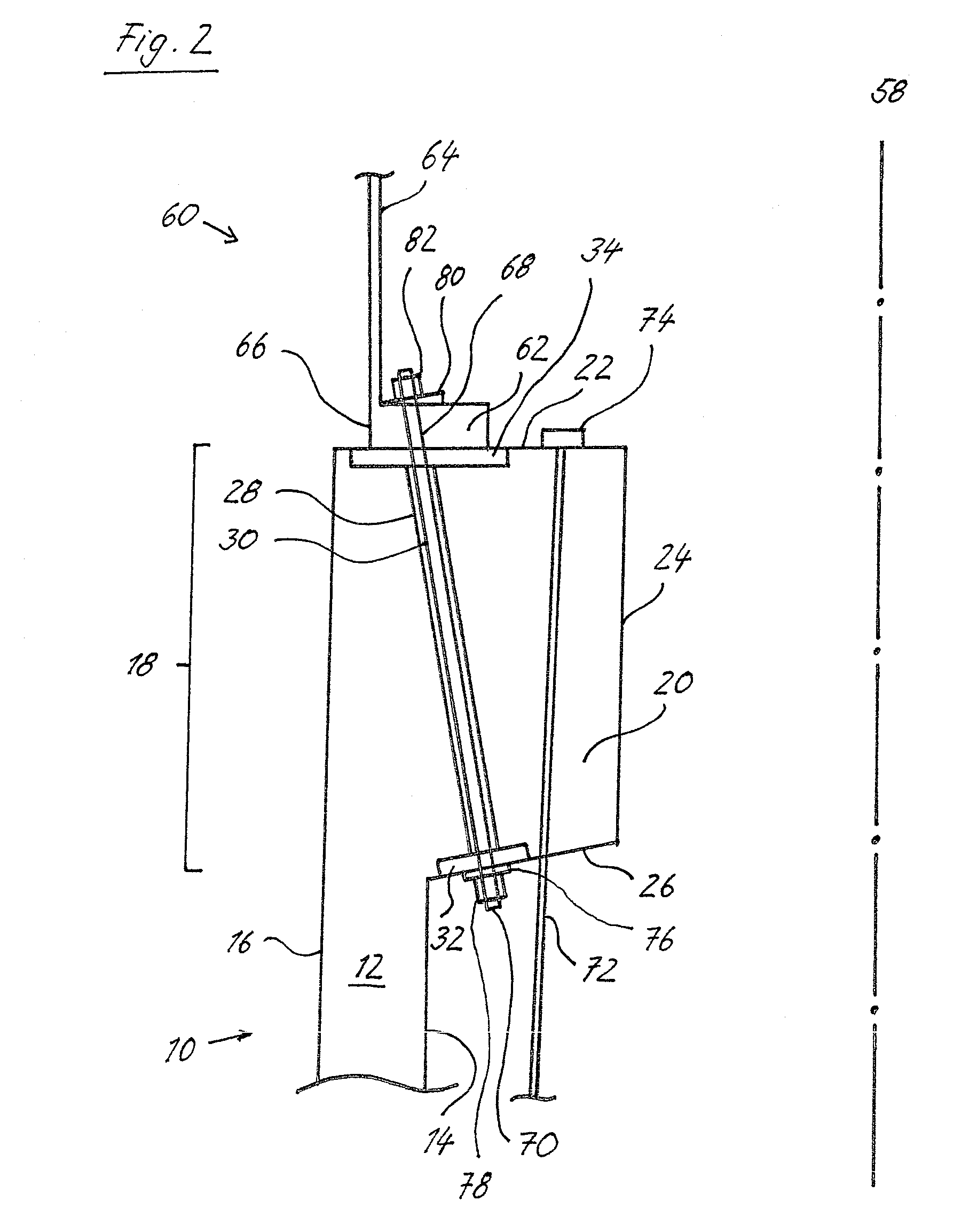
[0039]The cross sectional presentation of FIG. 2 shows a cut-out of the connection location between the steel-made tower segment 60 and the ...
PUM
 Abstract
Description
Claims
Application Information