Manifold assembly

a manifold and assembly technology, applied in the direction of couplings, applications, lighting and heating apparatus, etc., can solve the problems of reducing yield, and affecting the safety of equipmen

Inactive Publication Date: 2009-01-01
APPLIED MATERIALS INC
View PDF0 Cites 387 Cited by
  • Summary
  • Abstract
  • Description
  • Claims
  • Application Information

AI Technical Summary

Benefits of technology

[0007]Embodiments of a manifold assembly are provided herein. In some embodiments, a manifold assembly includes a first manifold having a first inlet, for coupling to a high temperature fluid source, and a first outlet; a second manifold having a second inlet and a second outlet; and a connector portion coupling the first outlet of the first manifold to the second inlet of the second manifold, the connector portion includes a polymer block; and a thermal isolator disposed between the polymer block and the first manifold.

Problems solved by technology

As such, the coupling block joining the mixing manifold where these fluids converge is often subject to high thermal stresses due to the high temperature process gas stream flowing through the coupling block as well as due to the temperature differential between the RPS manifold and the mixing manifold.
The thermal stresses generated in the coupling block may cause deformation, bending, and cracking of the PTFE block, which may lead to failure of the block and leakage of the process gases from the manifold assembly, thereby causing potential safety issues, equipment downtime, and lower yields.

Method used


Image

  • Manifold assembly
  • Manifold assembly
  • Manifold assembly

Examples


Embodiment Construction

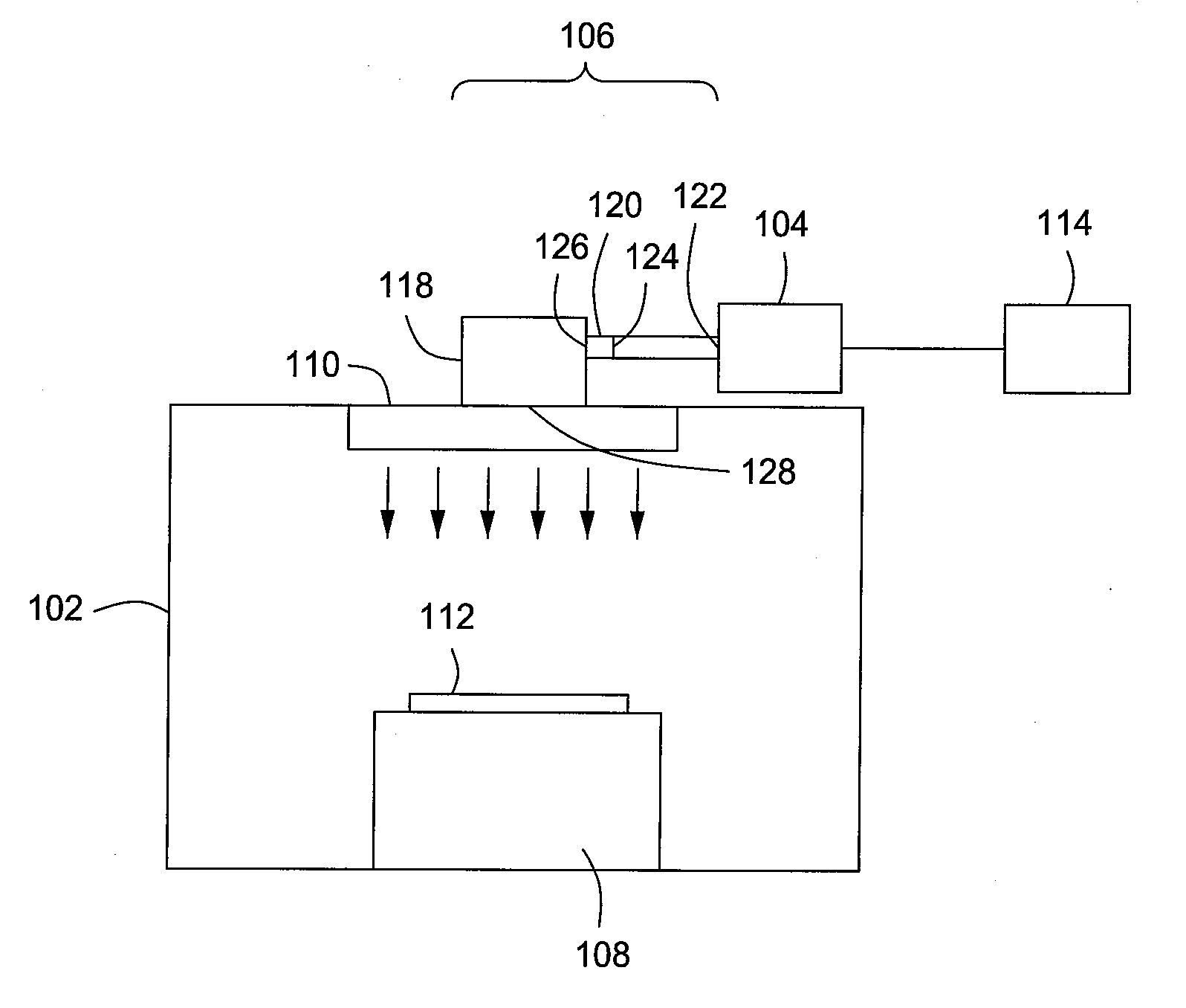
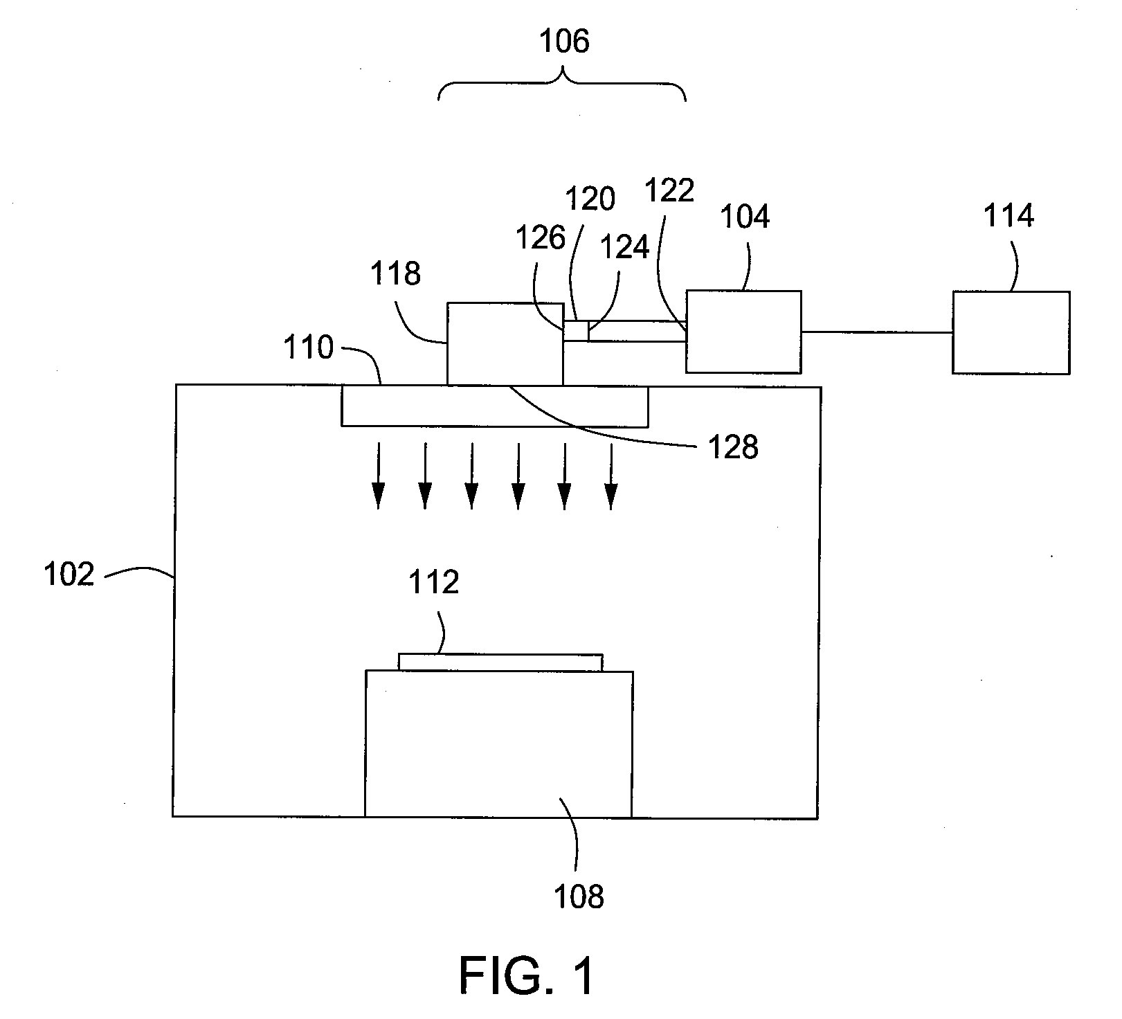
[0013]The present invention relates to a manifold assembly for conducting the flow of a fluid from a first chamber to a second chamber, wherein the first chamber is at a first temperature and the second chamber is at second temperature different from the first temperature. In some illustrative embodiments, a manifold assembly provides for the flow of fluids from a Remote Plasma Source (RPS) to a process chamber in a substrate processing apparatus, for example, a chemical vapor deposition (CVD) apparatus, or other apparatus utilizing a remote plasma source.

[0014]FIG. 1 illustrates a block diagram representing an illustrative substrate processing apparatus 100 in accordance with various embodiments of the present invention. The substrate processing apparatus 100 may be, for example, a chemical vapor deposition (CVD) apparatus, a low pressure, or sub-atmospheric, chemical vapor deposition (LPCVD or SACVD) apparatus, or the like. An example of an SACVD apparatus suitable for use with th...


PUM

PropertyMeasurementUnit
temperatureaaaaaaaaaa

Abstract

Embodiments of a manifold assembly are provided herein. In some embodiments, a manifold assembly includes a first manifold having a first inlet, for coupling to a high temperature fluid source, and a first outlet; a second manifold having a second inlet and a second outlet; and a connector portion coupling the first outlet of the first manifold to the second inlet of the second manifold, the connector portion includes a polymer block; and a thermal isolator disposed between the polymer block and the first manifold.

Description

BACKGROUND OF THE INVENTION[0001]1. Field of the Invention[0002]The present invention relates to a manifold assembly, and more particularly, to a manifold assembly for conducting the flow of a fluid from a first chamber at a first temperature to a second chamber at a lower temperature.[0003]2. Description of the Related Art[0004]In semiconductor processing, e.g., in the manufacture of integrated circuits, processes often occur that utilize high temperature fluids. For example, high temperature gases may be provided to a process chamber in which a semiconductor or other substrate is disposed for processing (e.g., for deposition, etching, or other processing of material layers disposed on the substrate). In some processes, these high-temperature fluids may be mixed with lower temperature fluids, or may be introduced into temperature controlled processing apparatus to control the temperature of the processing fluids as desired.[0005]For example, some process chambers may include a remo...

Claims


Application Information

Patent Timeline
Patent Type & Authority Applications(United States)
IPC IPC(8): H01L21/02F16L25/00F17D1/02F28F1/00
CPCF16L59/184Y10T137/87571Y10T137/9029
Inventor TRAN, TOAN Q.LUBORMIRSKY, DIMITRYTSUEI, LUN
Owner APPLIED MATERIALS INC
Why Eureka
Try Eureka