Positioning method of spot welding robot

Active Publication Date: 2009-01-01
FANUC LTD
View PDF2 Cites 24 Cited by
  • Summary
  • Abstract
  • Description
  • Claims
  • Application Information

AI Technical Summary

Benefits of technology

[0025]Thus, by applying the offset value obtained for one welding location as a offset value for other welding locations, new positions of spot welding point of the opposition electrode tip for a multiplicity of welding locations can be collectively obtained. In prior art, when an operator corrects the position of the spot welding point of the opposition electrode tip, correction of the position of spot welding point is carried out individually by moving the weldi

Problems solved by technology

If there is any gap, sputtering is induced during energization of the electrode tips, leading to degradation of welding quality.
However, the position of the work piece held by the jig or the like may be altered, or the thickness of the work piece may be changed, or the thickness of the work piece may be varied, and as a result, it may not be possible to sandwich the work piece between a pair of electrode tips without producing a gap.
Thus, a gap may be produced between the electrode tips and the work piece.
Thus, especially in the case of large spot welding gun having a mechanism of low rigidity, since the reaction force at the time of conta

Method used


Image

  • Positioning method of spot welding robot
  • Positioning method of spot welding robot
  • Positioning method of spot welding robot

Examples


Embodiment Construction

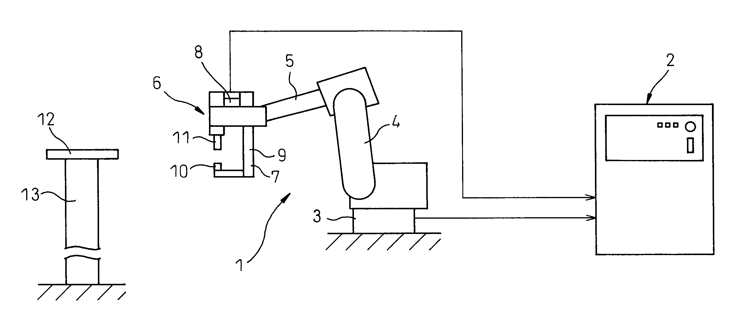
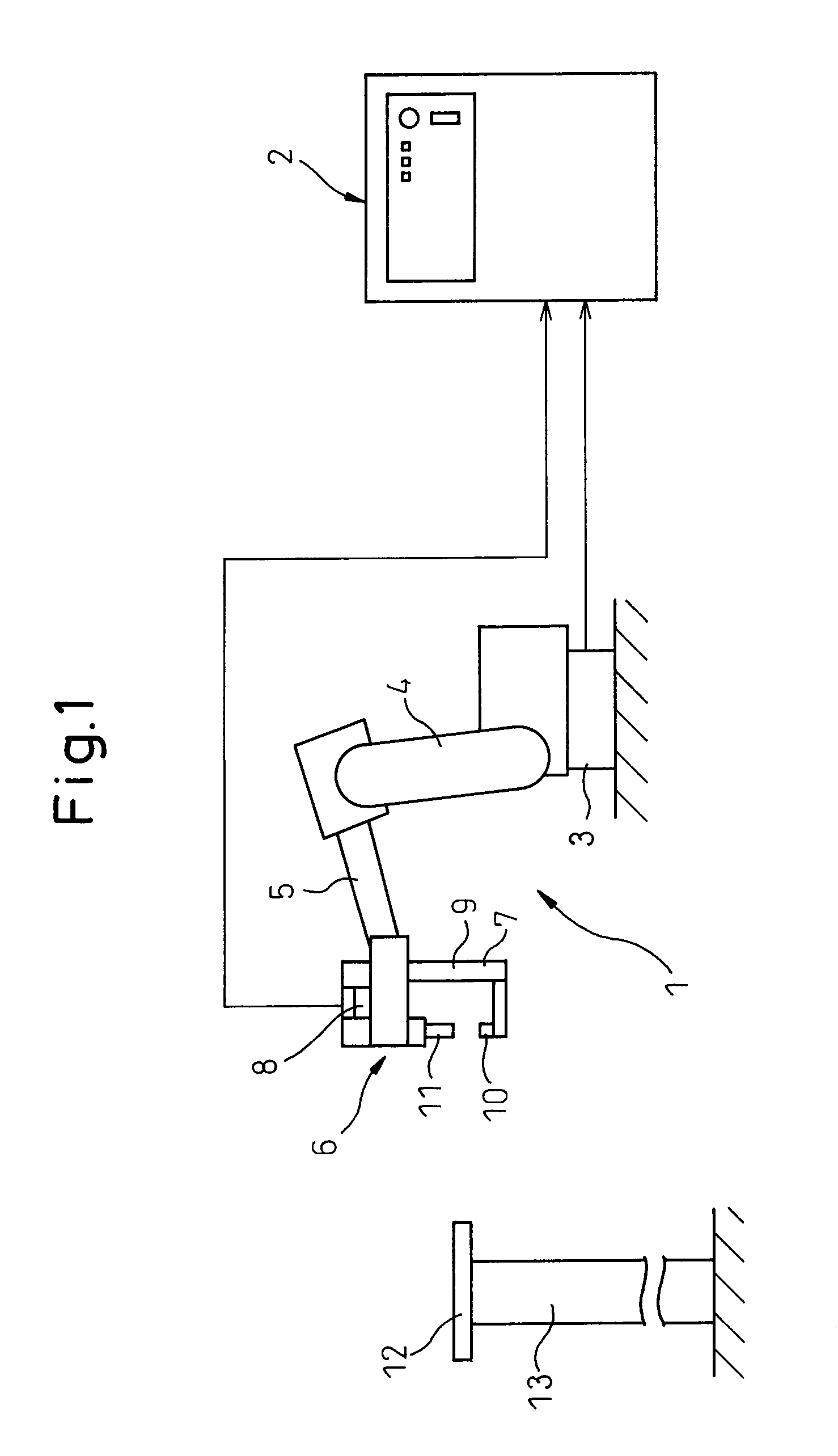
[0044]The present invention will be described in detail below with reference to drawings showing specific examples of a preferred embodiment. FIG. 1 is a processing system for carrying out a positioning method of a spot welding robot according to an embodiment of the present invention. The processing system includes a multi-joint type spot welding robot 1 and a robot controller 2 for controlling the spot welding robot, although the system may include other components. This processing system is adapted to position an opposition electrode tip to the position of spot welding point, that is, a position in contact with the lower surface of a work piece.

[0045]Spot welding robot 1 is a general 6 axes vertical multi-joint type robot, and has a base 3 fixed to a floor, a lower arm 4 connected to base 3, an upper arm 5 connected to lower arm 4, and a spot welding gun 6 rotatably provided at the distal end of upper arm 5. Lower arm 4 is mounted pivotably about a vertical first axis to base 3, ...


PUM

PropertyMeasurementUnit
Thicknessaaaaaaaaaa

Abstract

A positioning method of spot welding robot having: (A) moving a welding gun with a separation between an opposition electrode tip and a movable electrode tip kept open and larger than a preset plate thickness of a work piece so as to position the opposition electrode tip and the movable electrode tip on both sides of the work piece in a plate-thickness direction of the work piece, respectively, and temporarily positioning the opposition electrode tip at a stand-by position; (B) moving the movable electrode tip in a direction approaching toward the opposition electrode tip, monitoring the current value of the servo motor driving the movable electrode tip, and when the current value exceeds a prescribed value, determining that a distal end of the movable electrode tip has been brought into contact with the work piece, stopping a movement of the movable electrode tip and measuring an open separation of two opposing tips between the movable electrode tip and the opposition electrode tip that has been temporarily positioned at the stand-by position; and (C) determining the difference value by subtracting the preset value for the work piece from the open separation of two opposing tips, and moving the opposition electrode tip in the direction approaching toward the movable electrode tip from the stand-by position to the position of a spot welding point to finally position the opposition electrode tip, by using the difference value as the amount of movement of the opposition electrode tip.

Description

CROSS REFERENCE TO RELATED APPLICATIONS[0001]The present application claims the benefit of priority based on Japanese Patent Application No. 2007-160353, filed on Jun. 18, 2007, the disclosure of which is incorporated herein in its entirety by reference.BACKGROUND OF THE INVENTION[0002]1. Field of the Invention[0003]The present invention relates to a positioning method of a spot welding robot which has a pair of electrode tips, i.e., a movable electrode tip and an opposition electrode tip opposed to the movable electrode tip, and which sandwiches a work piece to be welded between the pair of electrode tips, and while applying pressure, welds the work piece.[0004]2. Description of Related Art[0005]In spot welding performed by a spot welding robot, in general, welding is performed on a work piece between a pair of opposing electrode tips, i.e., a movable electrode tip and an opposition electrode tip by applying a predetermined pressure to it. Thus, welding is performed on the work pie...

Claims


Application Information

Patent Timeline
IPC IPC(8): B23K37/02
CPCB23K11/315B23K11/253
Inventor TAKAHASHI, HIROMITSUAOKI, TOSHIMICHI
Owner FANUC LTD
Why Eureka
Try Eureka