Shock absorber

Active Publication Date: 2009-01-01
SMC CORP
View PDF12 Cites 23 Cited by
  • Summary
  • Abstract
  • Description
  • Claims
  • Application Information

AI Technical Summary

Benefits of technology

[0006]The technical problem of the present invention is, in a shock absorber having a cross-sectional area of a flow passage between an external periphery of a piston and an internal periphery of a tube, the cross-sectional area decreasing gradually toward the direction in which a piston rod is pushed in, to linearly increase a load applied to a fluid flowing

Problems solved by technology

However, this type of shock absorber, that is capable of controlling an amount of liquid flowing out in dependence of a piston stroke, has a configuration such that a liquid discharged from the compression side of the cylinder chamber, when the piston rod is moved toward the direction of being pushed in due to a mechanical impact applied to the piston rod, is transferred to between the inner tube and the outer tube; thereby the cylinder tube must consequentially be constructed to be double-walled, which results in a problem that the number of parts bec

Method used


Image

  • Shock absorber
  • Shock absorber
  • Shock absorber

Examples


Embodiment Construction

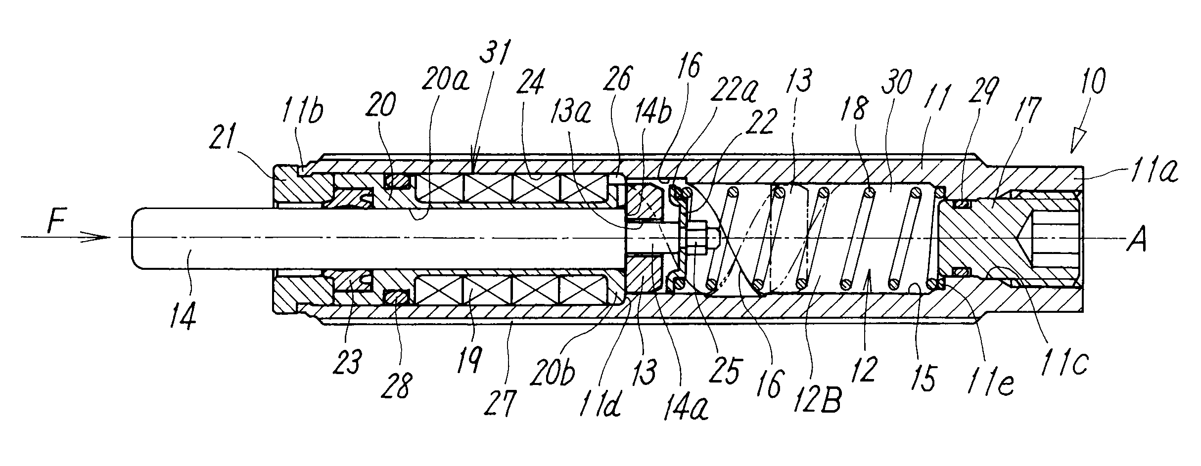
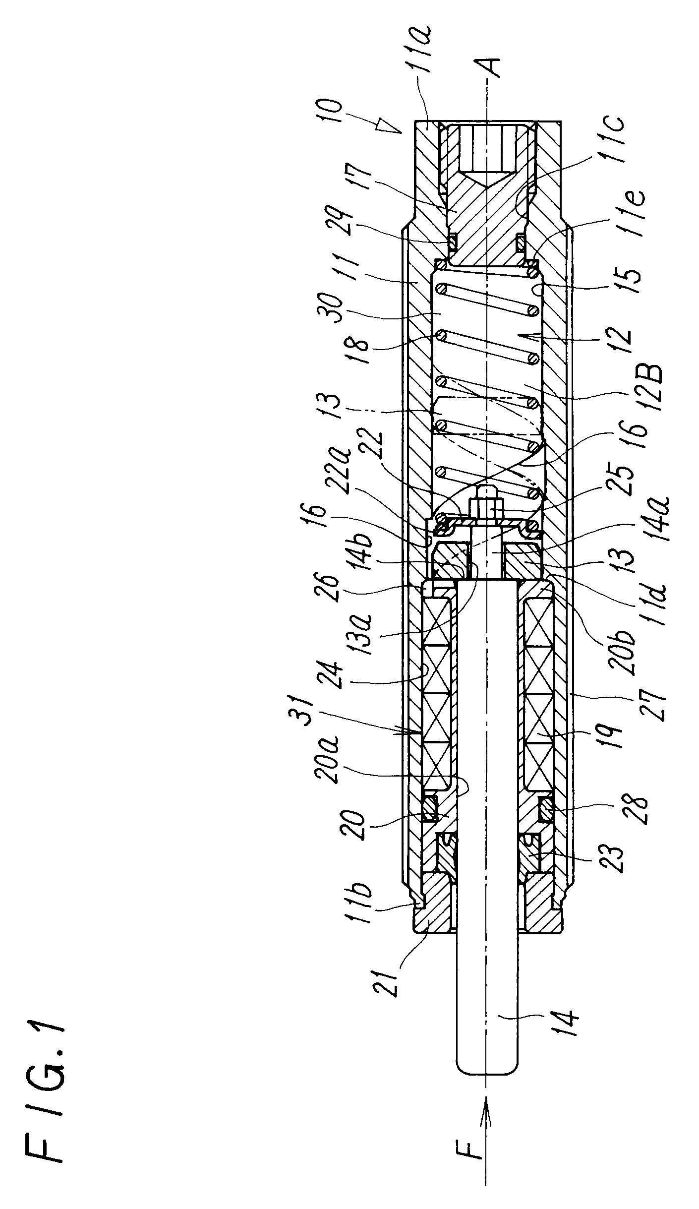
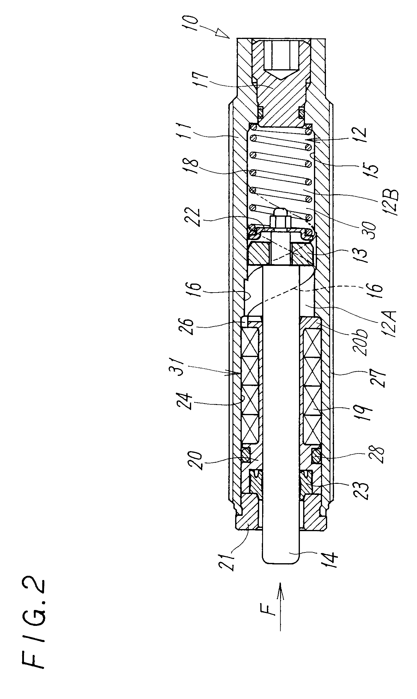
[0020]An embodiment of the present invention will now be described with reference to FIGS. 1 to 7. As shown in FIGS. 1 and 2, a shock absorber 10 of this embodiment has a cylindrical tube 11. A cylinder chamber 12 is formed in a half portion side (head side) of the tube 11 in the direction of its axis line A, a piston 13 connected to a piston rod 14 is inserted into the cylinder chamber 12 together with the piston rod 14 in the direction of the axis line A so as to be slidable, and the cylinder chamber 12 is divided by the piston 13 into the first cylinder chamber 12A on the side of the piston rod 14 and the second cylinder chamber 12B on the other side. Both ends of the cylinder chamber 12 are blocked by a flange portion 20b of a bearing casing 20, formed on a first end side of the bearing casing 20 in the direction of its axis line A, and a plug 17 screwed in an opening 11c on the head side end 11a of the tube 11, and the interior diameter of the cylinder chamber 12 is substantial...


PUM


Abstract

A cylinder chamber filled with a liquid, a piston disposed inside the cylinder chamber, a piston rod connected to the piston, and an accumulator allowing the piston rod to generate a damping force by receiving the liquid from a compression side of the cylinder chamber are included, and on an internal periphery of the cylinder chamber, one line of a helical damping groove is formed within a stroke range of the piston, a groove width of the damping groove is constant over the entire length of the damping groove, a depth of the damping groove gradually decreases along a spiral toward the direction in which the piston rod is pushed in, and a length of the piston in a direction along the axis line is smaller than a pitch of the damping groove.

Description

TECHNICAL FIELD[0001]The present invention relates to a shock absorber that allows a piston rod to generate a damping force by controlling an outflow of a liquid from the compression side of a cylinder chamber due to movement of a piston in the cylinder chamber, and absorbs a mechanical impact applied to the piston rod by the damping force.BACKGROUND ART[0002]A shock absorber that is previously well known from document 1 (Japanese Unexamined Utility Model Registration Application Publication No. S62-194946) or the like is provided with a cylinder chamber in a tube, the cylinder chamber enclosing a liquid therein, a piston dividing the cylinder chamber into two chambers, and a piston rod, one end of which is connected to the piston and the other end of which extends out from the tube, and allows the piston rod to generate a damping force by controlling an outflow of a viscous liquid from the compression side of the cylinder chamber due to sliding of the piston in the cylinder chamber...

Claims


Application Information

Patent Timeline
IPC IPC(8): F16F9/10
CPCF16F9/346F16F9/19F16F9/48
Inventor MIYASATO, EIKOSATO, SOICHI
Owner SMC CORP
Why Eureka
Try Eureka