
Motor Vehicle

a motor vehicle and motor technology, applied in the field of motor vehicles, can solve the problems of increased vehicle weight, increased assembly effort, and increased weight of bearing blocks, and achieve the effect of simple design

Inactive Publication Date: 2009-01-01
ZF FRIEDRICHSHAFEN AG
View PDF3 Cites 10 Cited by
  • Summary
  • Abstract
  • Description
  • Claims
  • Application Information

AI Technical Summary

Benefits of technology

[0006]The object of the present invention is to provide a connection of a Panhard rod or a longitudinal control arm, which is arranged between a vehicle chassis and a rigid axle associated with a rear axle arrangement, which connection effectively avoids the described drawbacks of the prior art and has a simple design.
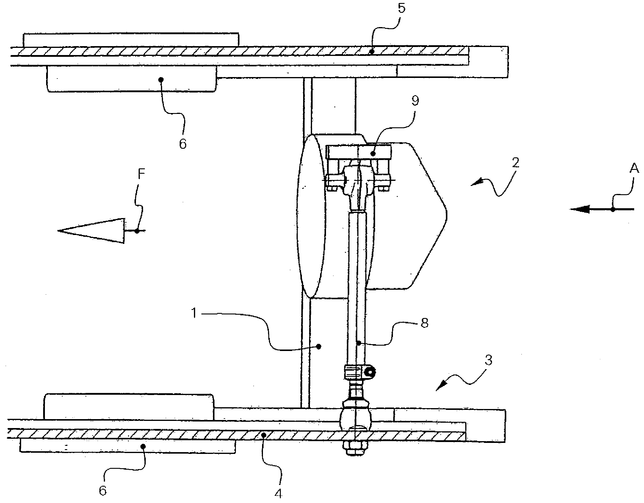
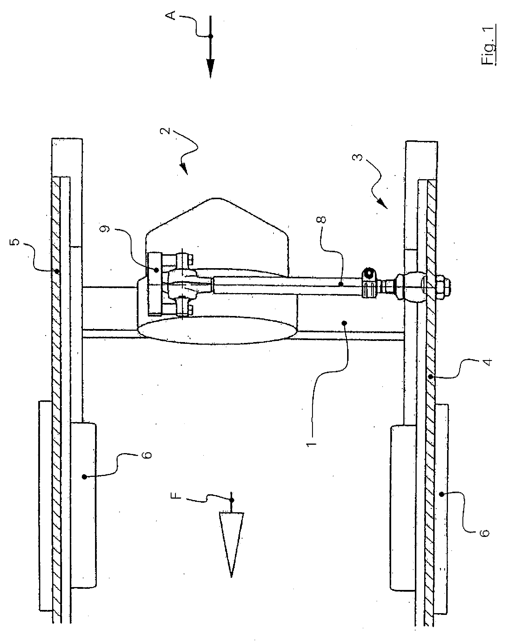
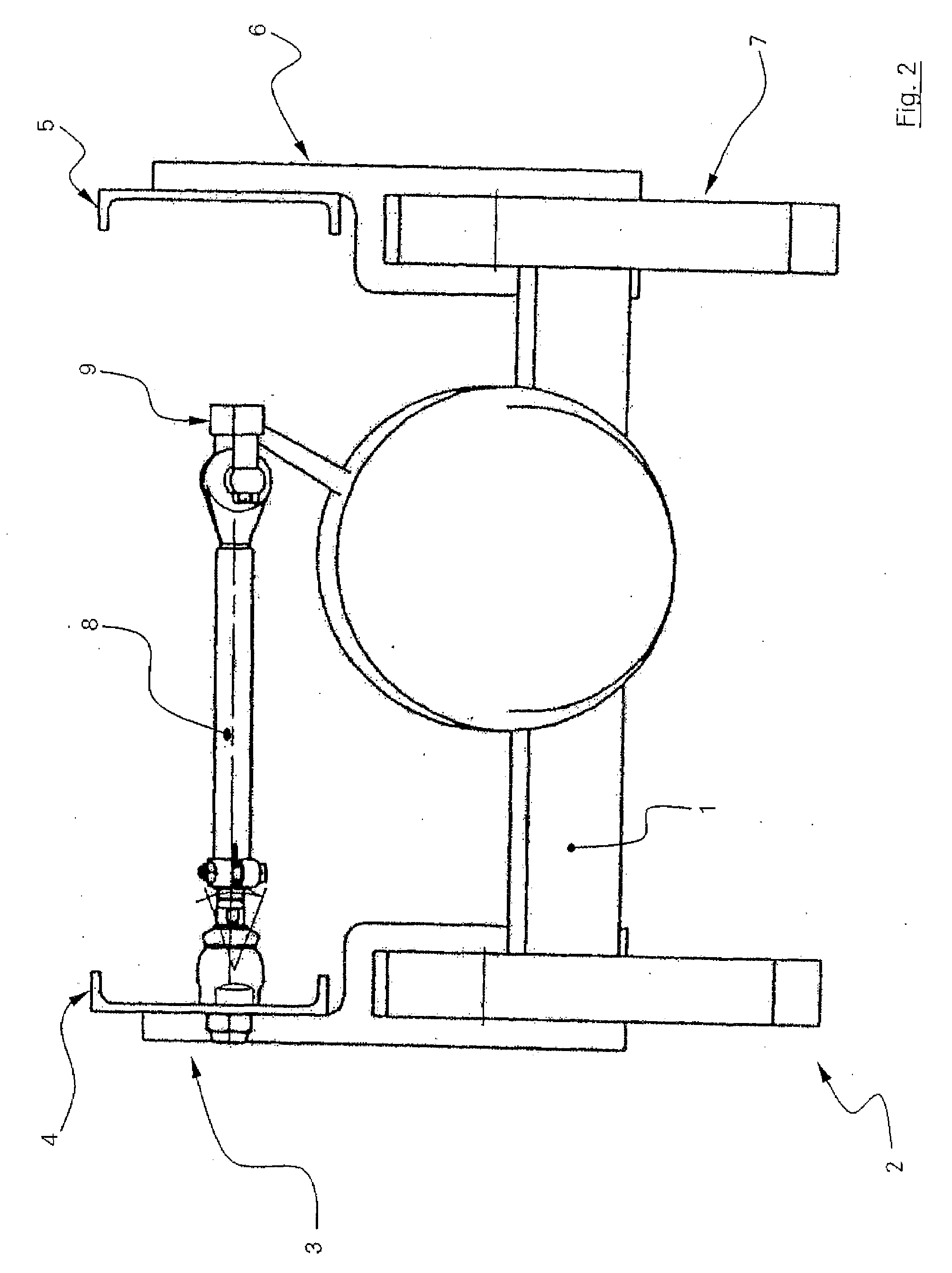
[0007]This object is accomplished, based on a motor vehicle according to the present invention with a Panhard rod arranged between the vehicle chassis as well as a rigid axle. The direct, pivotingly movable connection of the Panhard rod to the vehicle chassis with an axial joint. The use of bearing blocks, flanges or the like to connect the Panhard rod to the vehicle chassis is advantageously avoided due to this arrangement. In direct relationship hereto, this connection reduces the weight and the number of components and thus requires fewer assembly and manufacturing steps, as a result of which the costs are, on the whole, substantially reduced.
[0008]In an advantageous embodiment, the axial joint is designed as a ball and socket joint, where the ball and socket joint has a ball pivot with a joint ball. The joint ball is received in a bearing shell received in a bearing housing in a slidingly and pivotingly movable manner. The bearing housing is provided, furthermore, with a threaded bolt, which is received in a hole provided on the vehicle chassis. The bearing housing can thus be screwed to the vehicle chassis, for example, with a threaded nut by means of the threaded bolt. A wrench attachment is advantageously provided for this purpose on the bearing housing. This pivotingly movable connection makes it possible to compensate greater tolerances compared to the conventional connection because of the broad pivoting range of the axial joint. Furthermore, this form of connection minimizes the necessary connection parts and assembly steps to a minimum, as a result of which the manufacturing costs are further reduced.
[0009]In a preferred embodiment, the Panhard rod is formed from a tube with two joint pieces designed as a radial joint and an axial joint, wherein the joint pieces are inserted into the tube by means of a bearing journal or ball pivot associated with the joint piece. An additional tolerance compensation is achieved here by at least one joint piece being held displaceably in the tube, as a result of which longitudinal adjustment of the Panhard rod is made possible. The joint piece is held in an especially simple manner by means of a clamped connection between the tube and the end of the bearing journal or ball pivot of one of the two joint pieces, which said end is inserted into the tube. The clamped connection is preferably formed from a clip as well as a slotted end of the tube, which slotted end cooperates with the clip, wherein the clip compresses the slotted end of the tube against the end of the bearing journal or ball pivot of one of the two joint pieces, which said end is inserted into the tube.
[0010]If the motor vehicle according to the present invention is provided, for supporting longitudinal forces, with a control arm, for example, a longitudinal control arm, which is arranged between the rigid axle and the vehicle chassis, this is characterized by the direct, pivotingly movable articulation of the control arm to the rigid axle with an axial joint. Connection of the control arm to the rigid axle, which is held in a simple manner and comprises only a few individual parts, is achieved in this arrangement as well and the number of assembly and manufacturing steps is reduced in conjunction with a substantial cost reduction.

Problems solved by technology

The connection of the Panhard rod to the vehicle chassis, in particular, by means of a radial joint requires, on the chassis side, a separate bearing block, which causes a disadvantageous increase in the weight of the vehicle.
This bearing block requires, furthermore, an additional assembly effort due to screwing and / or welding operations, associated with additional attached parts and manufacturing steps.
The machining of flange or optionally cone connections is, in particular, very complicated, which leads to a disadvantageous increase in the costs.

Method used


Image

  • Motor Vehicle
  • Motor Vehicle
  • Motor Vehicle

Examples


Embodiment Construction

[0020]Referring to the drawings in particular, FIGS. 1 and 2 show two different views of the schematic design of a rear axle arrangement 2 having a rigid axle 1 with a vehicle chassis 3. The vehicle chassis 3 comprises here essentially a left and right longitudinal control arm 4, 5 each, which receives the spring 7 connecting the rigid axle 1 to the vehicle chassis via a bracket 6 each. A Panhard rod 8, which is connected on the axle side to a bracket 9 associated with the rigid axle 1, is arranged between the vehicle chassis 3 and the rigid axle 1. At the end of the Panhard rod 8 facing away from the rigid axle 1, the Panhard rod is articulated directly to the vehicle chassis 3.

[0021]As can be determined from FIG. 3 and FIG. 4, the Panhard rod 8 has a joint piece 10 each at the two ends, the axle-side joint piece 10 being designed as an axial joint 111 and the chassis-side joint piece 10 being designed as a radial joint 12. The radial joint 12 and the axial joint 11 are connected b...


PUM


Abstract

A motor vehicle, especially a utility vehicle, with a vehicle chassis (3) as well as with a rear axle arrangement (2) having a rigid axle (1). A Panhard rod (8) for supporting lateral forces or a control arm for supporting longitudinal forces is arranged between the vehicle chassis (3) and the rigid axle (1). The motor vehicle has the Panhard rod (8), which is directly articulated to the vehicle chassis (3) with an axial joint (11) in a pivotingly movable manner or by a control arm. The Panhard rod (8) is articulated to the rigid axle directly with an axial joint (11) in a pivotingly movable manner.

Description

CROSS REFERENCE TO RELATED APPLICATIONS[0001]This application is a United States National Phase application of International Application PCT / DE 2004 / 002254 and claims the benefit of priority under 35 U.S.C. § 119 of German Application DE 103 48 645.3 filed Oct. 15, 2003, the entire contents of which are incorporated herein by reference.FIELD OF THE INVENTION[0002]The present invention pertains to a motor vehicle, especially a utility vehicle, with a vehicle chassis and a rear axle arrangement having a rigid axle. A so-called Panhard rod is arranged here between the vehicle chassis and the rigid axle. In addition or in alternative rear axle arrangements, a longitudinal control arm arranged between the axle and the vehicle chassis may be used.BACKGROUND OF THE INVENTION[0003]Rear axle arrangements with a rigid axle continue to be used in motor vehicles, especially utility vehicles, with a vehicle chassis. To support lateral forces acting on the rear axle, which result, for example, fr...

Claims


Application Information

Patent Timeline
IPC IPC(8): B60G7/00B60G9/00
CPCB60G7/001B60G7/005B60G9/00B60G2200/30B60G2200/314B60G2206/91B60G2204/143B60G2204/416B60G2204/4404B60G2206/012B60G2206/1112B60G2200/341
Inventor BUHL, REINHARDRICHTER, REINHARDSCHMUDDE, WERNER
Owner ZF FRIEDRICHSHAFEN AG
Learn More