LED lamp module

a technology of led lamps and modules, applied in the field of light sources, can solve the problems of large prior art devices, difficult to provide the proper light distribution to achieve the desired purpose, and high cost of prior art devices

Inactive Publication Date: 2009-01-01
OSRAM SYLVANIA INC
View PDF16 Cites 123 Cited by
  • Summary
  • Abstract
  • Description
  • Claims
  • Application Information

AI Technical Summary

Benefits of technology

[0009]This unit achieves the long life expectancy provided by light emitting diodes and the plural-function lens directs the light from the LEDs and the paraboloidal reflector in the proper manner.

Problems solved by technology

Such lights have employed incandescent light bulbs as the light source and these light sources have been subjected to occasional failure at inopportune times. Further, it has been difficult to provide the proper light distribution to achieve the desired purpose.
These prior art devices have been large and expensive.

Method used


Image

  • LED lamp module
  • LED lamp module
  • LED lamp module

Examples


Embodiment Construction

[0013]For a better understanding of the present invention, together with other and further objects, advantages and capabilities thereof, reference is made to the following disclosure and appended claims taken in conjunction with the above-described drawings.

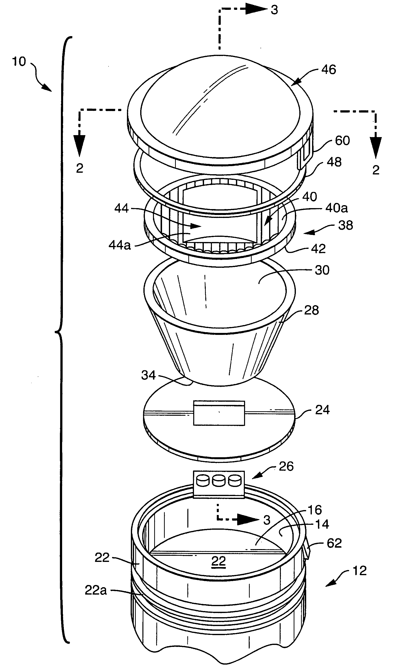
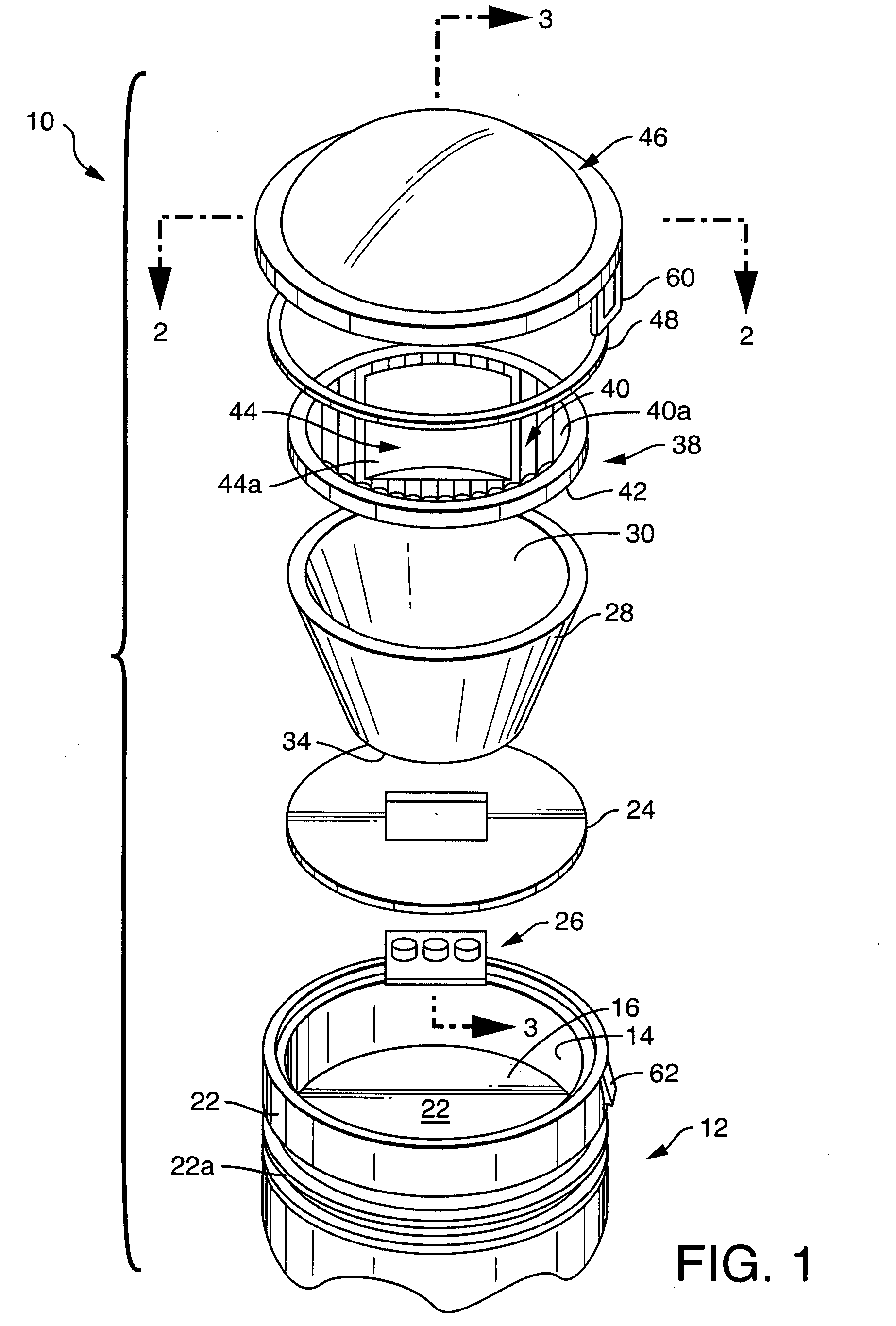
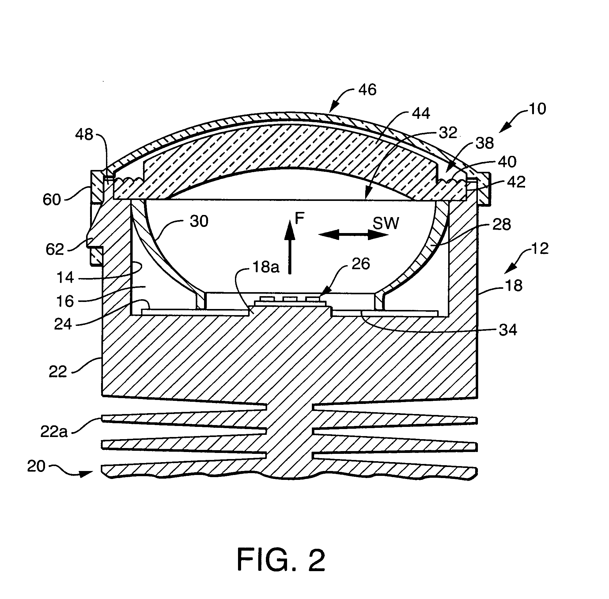
[0014]Referring now to the drawings with greater particularity, there is shown in FIG. 1 an LED lamp 10, that can be, for example, a fog lamp, comprising a housing 12 with an interior wall 14 defining a cavity 16 providing an opening facing a forward direction “F”, the cavity 16 having a back wall 18. The housing 12, which preferably is made from a suitable metal, such as aluminum, includes a heat sink 20 extending on an exterior side 22 of the back wall 18.

[0015]An LED light source 26 is fixed to the back wall 18, preferably upon a boss 18a (shown best in FIGS. 2 and 3) and projects light in the forward direction “F” and sideways directions “SW” up to 90 degrees from the forward direction “F”. While three LEDs are shown in FIGS....


PUM


Abstract

An LED lamp (10) has a housing (12) with an interior wall (14) defining a cavity (16). An LED light source (26) is positioned in the cavity (16) and project light in a forward direction. A reflector (28) having a reflective surface (30), a forward opening (32) and a rear opening (34) surrounds the light source (26) and a complex lens (38) closes the forward opening. The lens (38) comprises a first optical refractive element (40) arranged around a peripheral edge (42) and a second optical refractive element (44) centrally located on the lens (38); the first optical refractive element (40) including a plurality of flute lenses (40a) and the second optical refractive element (44) comprising a concavo-convex lens (44a).

Description

CROSS-REFERENCE TO RELATED APPLICATION[0001]This application claims priority from Provisional Patent Application Ser. No. 60 / 937,845, filed Jun. 30, 2007.TECHNICAL FIELD[0002]This application relates to light sources and more particularly to light emitting diode (LED) light sources. Still more particularly it relates to automotive light sources that are modularized, such, for example as may particularly be adapted for use in foggy conditions.BACKGROUND ART[0003]Lights have been provided motor vehicles virtually since their inception. Such lights have employed incandescent light bulbs as the light source and these light sources have been subjected to occasional failure at inopportune times. Further, it has been difficult to provide the proper light distribution to achieve the desired purpose. Additionally, the optics employed by some of these prior art lights, in particular, fog lights, were either reflectors or projectors. Projectors use a reflector to collect the light and image it...

Claims


Application Information

Patent Timeline
Patent Type & Authority Applications(United States)
IPC IPC(8): F21V7/00B60Q1/00F21K99/00
CPCF21K9/00F21S48/1233F21V29/74F21Y2101/02F21V3/00F21W2101/10F21K9/69F21Y2115/10F21S41/143F21S41/151F21S41/28F21S41/29F21S41/321F21S45/10F21S45/48F21S45/47F21W2102/00
Inventor TESSNOW, THOMASTUCKER, MIKEMADHANI, VIPINFREY, PETER
Owner OSRAM SYLVANIA INC
Why Eureka
Try Eureka