Cleaning device, fixing device, and image forming apparatus

a technology of fixing device and cleaning device, which is applied in the direction of electrographic process apparatus, instruments, optics, etc., can solve the problems of inability to follow the surface roughness, inability to produce an uneven image, and large number of toner particles which are neither transferred nor fixed on the fixing member, so as to avoid uneven production, prolong the warm-up time, and remove toner particles reliably

Inactive Publication Date: 2009-01-01
RICOH KK
View PDF15 Cites 27 Cited by
  • Summary
  • Abstract
  • Description
  • Claims
  • Application Information

AI Technical Summary

Benefits of technology

[0031]Accordingly, example embodiments of the present invention provide a cleaning device that can reliably remove toner particles adhered to or remaining on a cleaning target withou

Problems solved by technology

In particular, when a recording medium having a rough surface is used for an image forming apparatus which performs transfer and fixing processes separately, an intermediate transfer member such as an intermediate transfer belt cannot follow the surface roughness of the recording medium.
Since abnormal discharge tends to occur in the microgap, a toner image on the intermediate transfer member may be abnormally transferred onto the recording medium, resulting in production of an uneven image.
Consequently, when a paper jam occurs in an image forming apparatus employing the transfixing device, an extremely large number of toner particles which are neither transferred nor fixed may remain on the fixing member (i.e., a cleaning target).
In addition, undesired toner particles adhered to non-image portions also remain on the fixing member, and cause background fouling in the resultant image.
If the toner block is broken, fragments thereof may not be sufficiently removed from the cleaning member, and may strongly adhere to or remain on part of the cleaning member.
As a result, the cleaning target and the cleaning member may be in uneven contact with each other or the leading edge of the blade member may be damaged.
However, this technique may waste time and electric power for melting the toner block, and there is also the cost of providing the heater.
However, this technique has a drawback in that the ability of the cleaning blade to remove remaining toner particles from the

Method used


Image

  • Cleaning device, fixing device, and image forming apparatus
  • Cleaning device, fixing device, and image forming apparatus
  • Cleaning device, fixing device, and image forming apparatus

Examples


Embodiment Construction

[0055]Example embodiments will now be described in detail referring to the drawings, wherein like reference numerals designate identical or corresponding parts throughout the several views thereof.

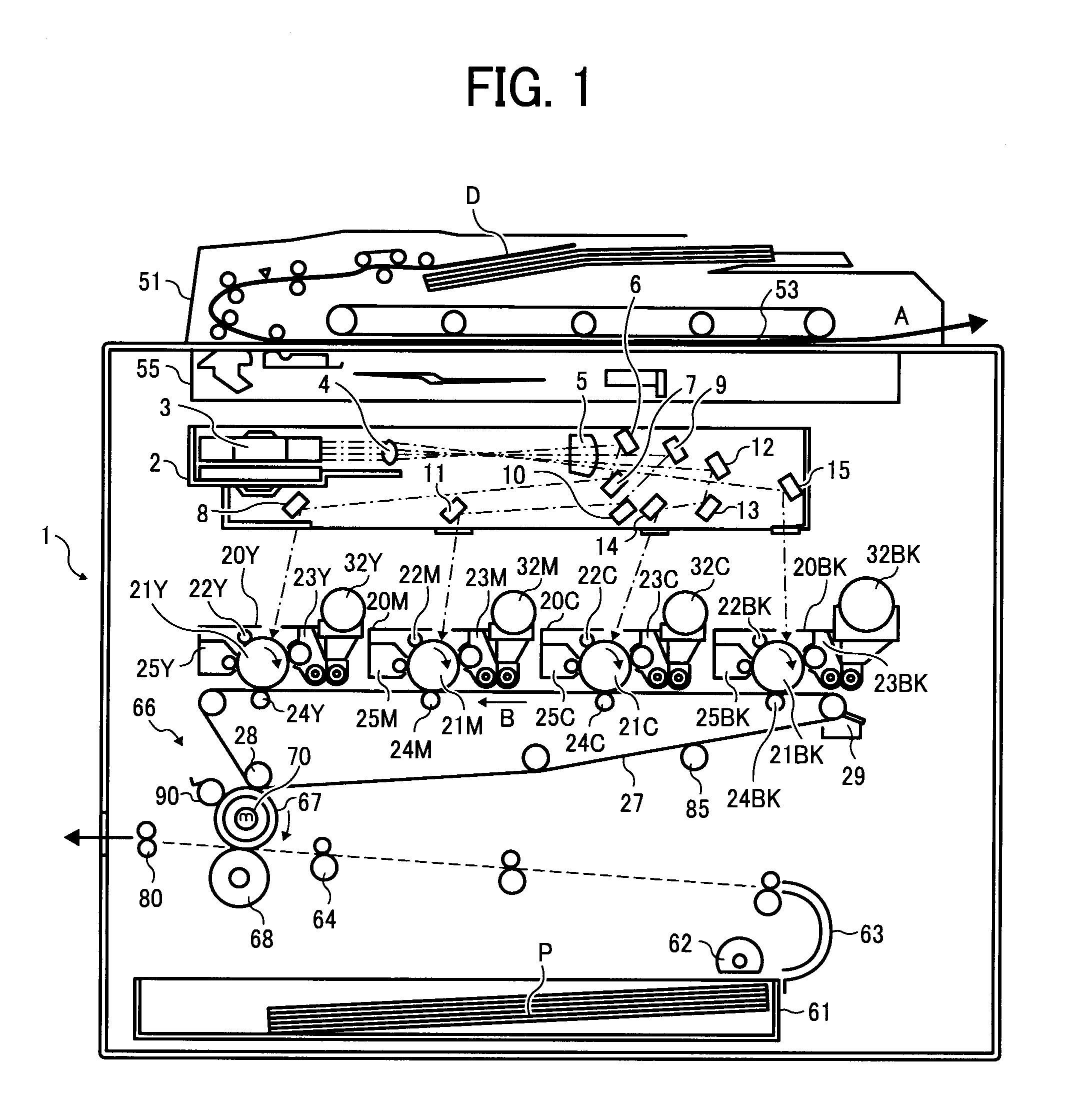
[0056]FIG. 1 is a schematic view illustrating an image forming apparatus according to an example embodiment of the present invention. A main body 1 of a color copier serving as an image forming apparatus houses a writing unit (i.e., a light emitting unit) 2 configured to emit a laser light beam based on image information acquired from a read image; process cartridges 20Y, 20M, 20C, and 20 BK respectively forming images of yellow, magenta, cyan, and black toner; photoconductors (i.e., image bearing members) 21Y, 21M, 21C, and 21BK respectively included in the process cartridges 20Y, 20M, 20C, and 20 BK; chargers 22Y, 22M, 22C, and 22BK configured to charge the photoconductors 21Y, 21M, 21C, and 21BK, respectively; developing devices 23Y, 23M, 23C, and 23BK configured to develop an electrost...


PUM


Abstract

A cleaning device including a cleaning member that moves in a predetermined direction and is in contact with a cleaning target that moves in a predetermined direction and which is directly or indirectly heated by a heater, to remove toner particles on a surface of the cleaning target. A contact surface of the cleaning member with the cleaning target includes a plurality of regions of different toner-releasing ability.

Description

CROSS-REFERENCE TO RELATED APPLICATIONS[0001]This document claims priority from and contains subject matter related to Japanese Patent Applications Nos. 2007-165709 and 2007-194245, filed on Jun. 23, 2007 and Jul. 26, 2007, respectively, the entire contents of each of which are hereby incorporated herein by reference.BACKGROUND[0002]1. Field of the Invention[0003]The present invention relates to a cleaning device for removing toner particles adhered to or remaining on a cleaning target which is directly or indirectly heated by a heater, and a fixing device and an image forming apparatus using the cleaning device.[0004]2. Description of the Background[0005]Electrophotographic image forming apparatuses, such as copiers, printers, facsimile machines, and multifunctional peripherals, equipped with a transfixing device which simultaneously performs a transfer process and a fixing process, are known. For example, Unexamined Japanese Patent Application Publication No. (hereinafter “JP-A”) ...

Claims


Application Information

Patent Timeline
IPC IPC(8): G03G15/20
CPCG03G21/0011G03G15/2025G03G2215/1676
Inventor KAYAHARA, SHINFUJITA, TAKASHITAKEMOTO, TAKESHITAKAGAKI, HIROMITSUSETO, TAKASHISUZUKI, KAZUMINAGATA, ATSUSHI
Owner RICOH KK
Why Eureka
Try Eureka