Radio frequency receiving apparatus, radio frequency receiving method, LSI for radio frequency signal and LSI for base band signal

a radio frequency and receiving device technology, applied in the direction of amplifiers with semiconductor devices/discharge tubes, gain control, transmission, etc., can solve the problems of deteriorating the received signal and line quality, unable to perform proper gain control, and unable to achieve the maximum gain of the re variable gain amp

Active Publication Date: 2009-01-01
LAPIS SEMICON CO LTD
View PDF3 Cites 9 Cited by
  • Summary
  • Abstract
  • Description
  • Claims
  • Application Information

AI Technical Summary

Benefits of technology

[0013]To achieve this object, according to the present invention, there is also provided a receiving apparatus including an RF variable gain Amp that amplifies a received RF signal; a conversion circuit that converts an output signal of the RF variable gain Amp into an IF signal; an IF variable gain Amp that amplifies an output signal of the conversion circuit; a demodulation circuit that demodulates an output signal of the IF variable gain Amp; and an AGC circuit. The AGC circuit sets a period of gain control for the RF variable gain Amp to be shorter than a period of gain control for the IF variable gain Amp, whereby respective gain of the RF variable gain Amp and the IF variable gain Amp are controlled based on the output signal of the IF variable gain Amp.
[0014]According to the present invention, since the period of gain control of the RF variable gain Amp is set to be shorter than the period of gain control of the IF variable gain Amp, saturated amplification that may occur due to interference power may be avoided by suppressing the gain of the RF variable gain Amp following sudden change of received power. In addition, since it is possible to control the gain of the IF variable gain Amp at high speed, it is possible to follow fast changes of received signal power which occur during fast movement of the receiver.

Problems solved by technology

However, the receiving methods and apparatuses as noted above have the following problems.
However, in such a gain changing method, since an RF gain variable range is different from an IF gain variable range, it is not possible to perform proper gain control due to a difference between RF response speed and IF response speed.
However, in the absence of a filter that limits a frequency band to a desired signal band, undesired signals may occur due to saturated amplification, thereby deteriorating the received signal and line quality.
However, in the conventional receiving method, as shown in FIG. 6, when the power of the interference is large compared to the small power of the desired received signal, the gain of the RE variable gain Amp becomes maximal, which results in a higher possibility of saturated amplification due to signal interference.
In this case, when the signals CH0, CH1 and CH2 are amplified, the desired signal CH0 interferes with the amplified adjacent channel signals CH1 and CH2, which results in deterioration of reception quality of the desired signal CH0.

Method used


Image

  • Radio frequency receiving apparatus, radio frequency receiving method, LSI for radio frequency signal and LSI for base band signal
  • Radio frequency receiving apparatus, radio frequency receiving method, LSI for radio frequency signal and LSI for base band signal
  • Radio frequency receiving apparatus, radio frequency receiving method, LSI for radio frequency signal and LSI for base band signal

Examples


first embodiment

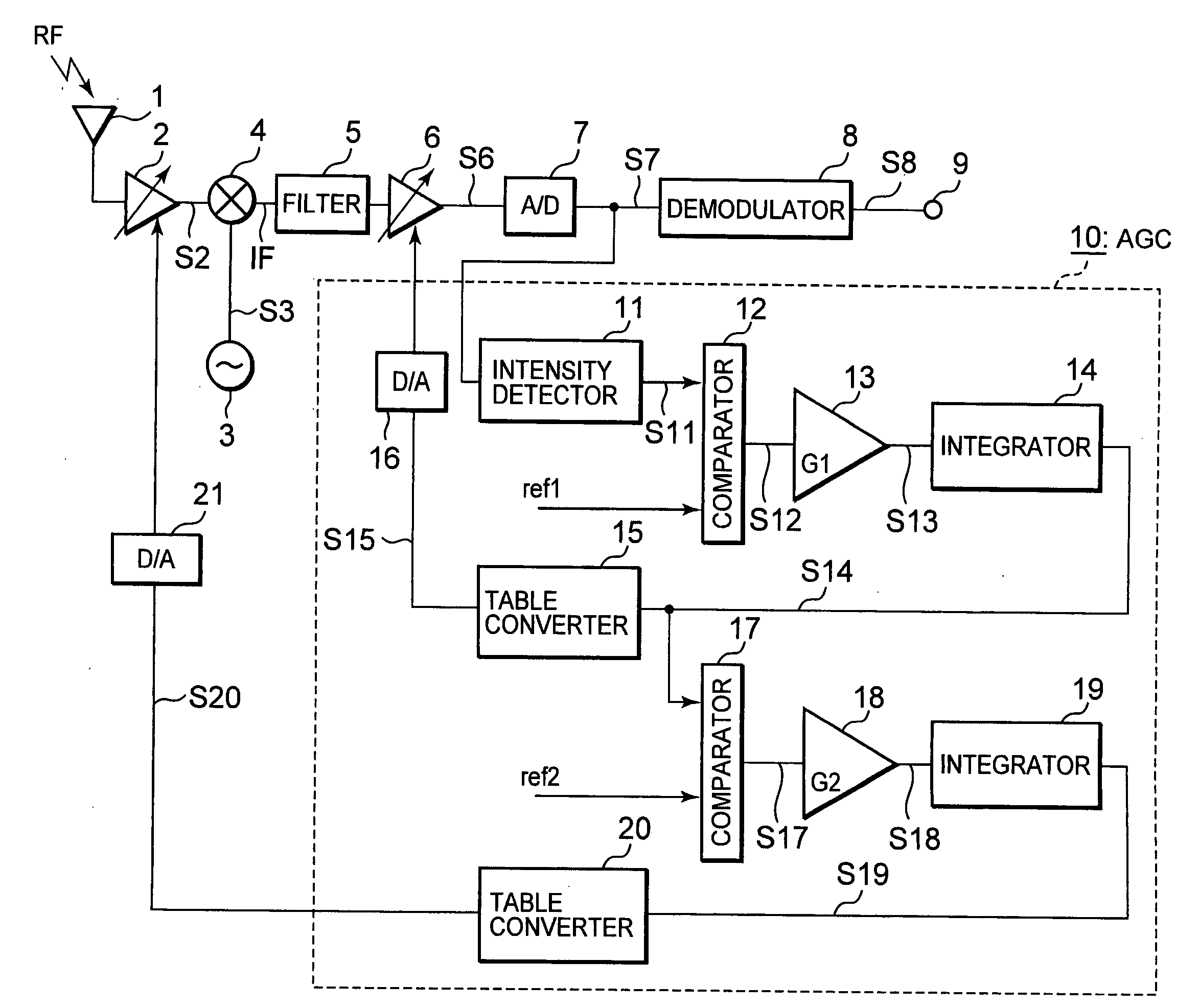
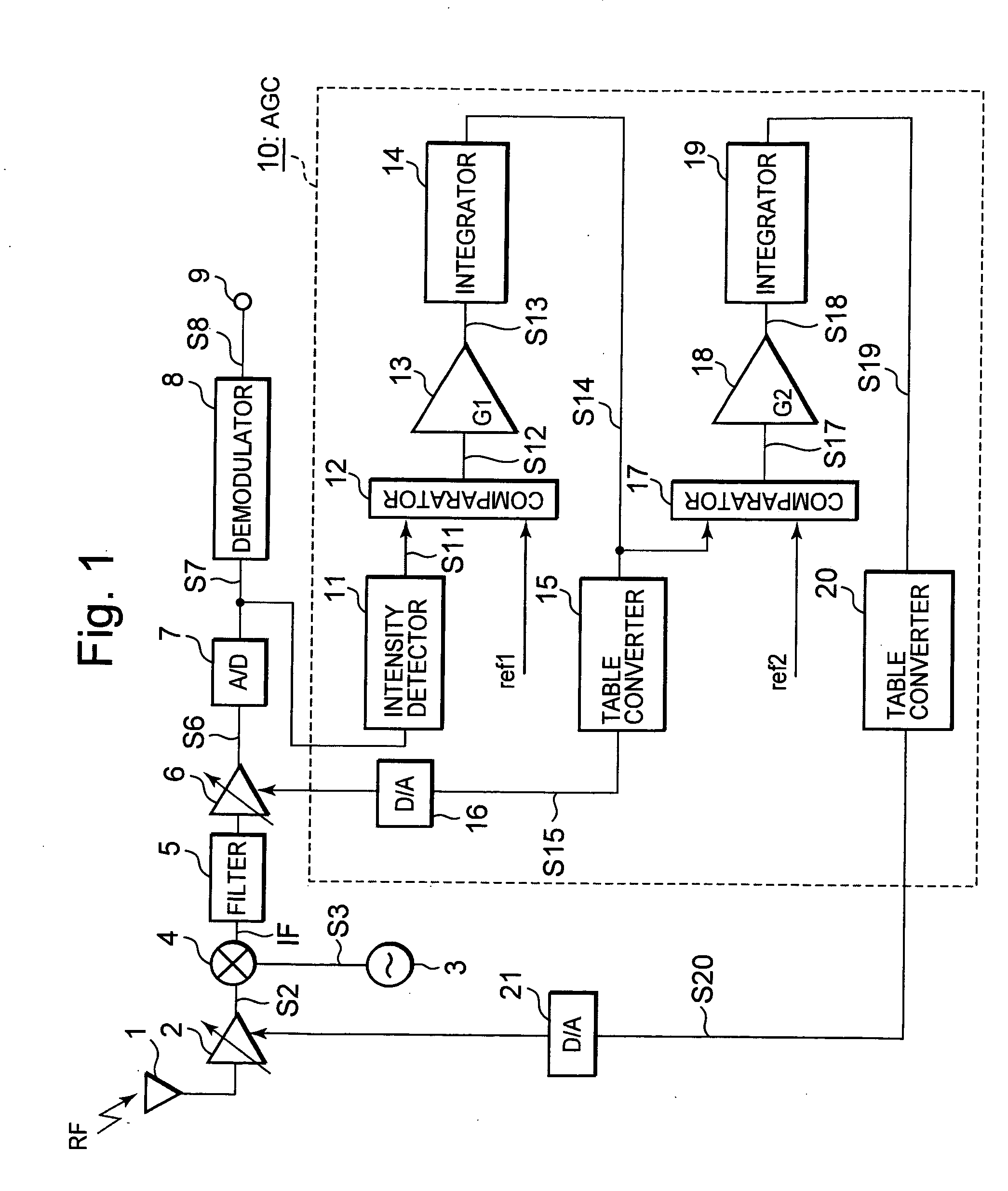
[0024]FIG. 1 is a schematic view showing a configuration of a receiving apparatus according to the present invention. The receiving apparatus, which is configured by large scale integration (LSI) or the like, includes an antenna 1 that receives an RF signal such as a terrestrial digital broadcasting wave or the like, an RF variable gain Amp 2 connected to the antenna 1, a local oscillator 3 that outputs a local oscillating signal S3 having a predetermined frequency, and a mixer 4 connected to outputs of RF variable gain Amp 2 and local oscillator 3. Local oscillator 3 and mixer 4 together form a conversion circuit. RF variable gain Amp 2, which is for example configured by an LNA, amplifies the RF signal received by antenna I based on gain set by gain control signal S19 fed back from AGC circuit 10, and outputs an output signal S2 to mixer 4. Mixer 4 mixes the output signal S2 with local oscillating signal S3 and outputs an IF signal, which is provided to IF variable gain Amp 6 via ...

second embodiment

[0042] since the response speed of the gain control (RF-AGC) for RF variable gain Amp 2 is varied depending on the moving speed of the mobile receiver, it is possible to achieve proper gain control according to the moving speed of the mobile receiver, thereby improving reliability of the moving receiver.

[0043]The present invention is not limited to the above described embodiments. For example, other different uses and modifications are possible, such as excluding filter 5 from the receiving apparatus, adding the functions of different circuits, and changing the configuration of AGC circuits 10 and 10A, and changing the receiving method according to such change. These modifications can be made to the embodiments described above will still falling within the scope of the appended claims.


PUM


Abstract

A receiving apparatus may achieve optimal RF and IF gain control while suppressing saturated amplification due to interference. The receiving apparatus includes an RF variable gain Amp that amplifies a received RF signal, a mixer that converts an output signal of the RF variable gain Amp into an IF signal, an IF variable gain Amp that amplifies the IF signal, a demodulator that demodulates an output signal of the IF variable gain Amp, and an AGC circuit. The AGC circuit sets a period of gain control for the RF variable gain Amp to be shorter than a period of gain control for the IF variable gain Amp when gains of the RF variable gain Amp and the IF variable gain Amp are controlled based on the output signal of the IF variable gain Amp.

Description

BACKGROUND OF THE INVENTION[0001]1. Field of the Invention[0002]The present invention relates to a receiving apparatus and a receiving method for receiving a radio frequency (RF) signal such as, for example, a terrestrial digital broadcasting wave and the like in mobile terminals, vehicle-mounted terminals and so on while moving or at stationary sites, an LSI (Large Scale Integration) for a radio frequency signal, and an LSI for a base band signal. More particularly, the present invention relates to an AGC independent control technique for selecting a channel of an RF signal received by an antenna, and performing an automatic gain control (AGC) for RF amplification and intermediate frequency (IF) amplification in an RF unit independently. This application claims priority under 35 U.S.C. §119 to Japanese Patent Application Serial No. 2007-167508 filed Jun. 26, 2007, the entire disclosure of which is hereby incorporated by reference herein.[0003]2. Description of the Related Art[0004]...

Claims


Application Information

Patent Timeline
Patent Type & Authority Applications(United States)
IPC IPC(8): H04B1/26
CPCH04B1/28H04B1/18
Inventor AKAHORI, HIROJI
Owner LAPIS SEMICON CO LTD
Why Eureka
Try Eureka