Compression, thermal and support bandaging system

a compression and support bandaging technology, applied in the field of therapeutic equipment, can solve problems such as not staying in place very well

Inactive Publication Date: 2009-01-01
CLINICAL TECH N Z
View PDF9 Cites 44 Cited by
  • Summary
  • Abstract
  • Description
  • Claims
  • Application Information

AI Technical Summary

Benefits of technology

[0008]In a first broad aspect the invention provides a re-usable compression, thermal and support bandaging system (the thermal aspect being optional), wherein the system includes a main bandage having an approximately central wider area having a breadth, a width, an outer and an inner surface; joined to two long flexible straps each having a free end and a joined end; each strap extending in opposite directions from diagonall

Problems solved by technology

It would not stay

Method used


Image

  • Compression, thermal and support bandaging system
  • Compression, thermal and support bandaging system
  • Compression, thermal and support bandaging system

Examples


example 1

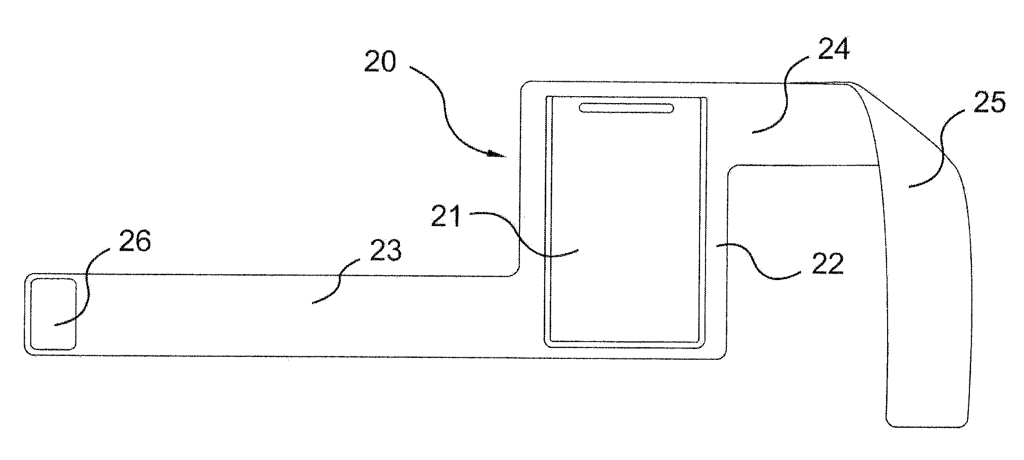
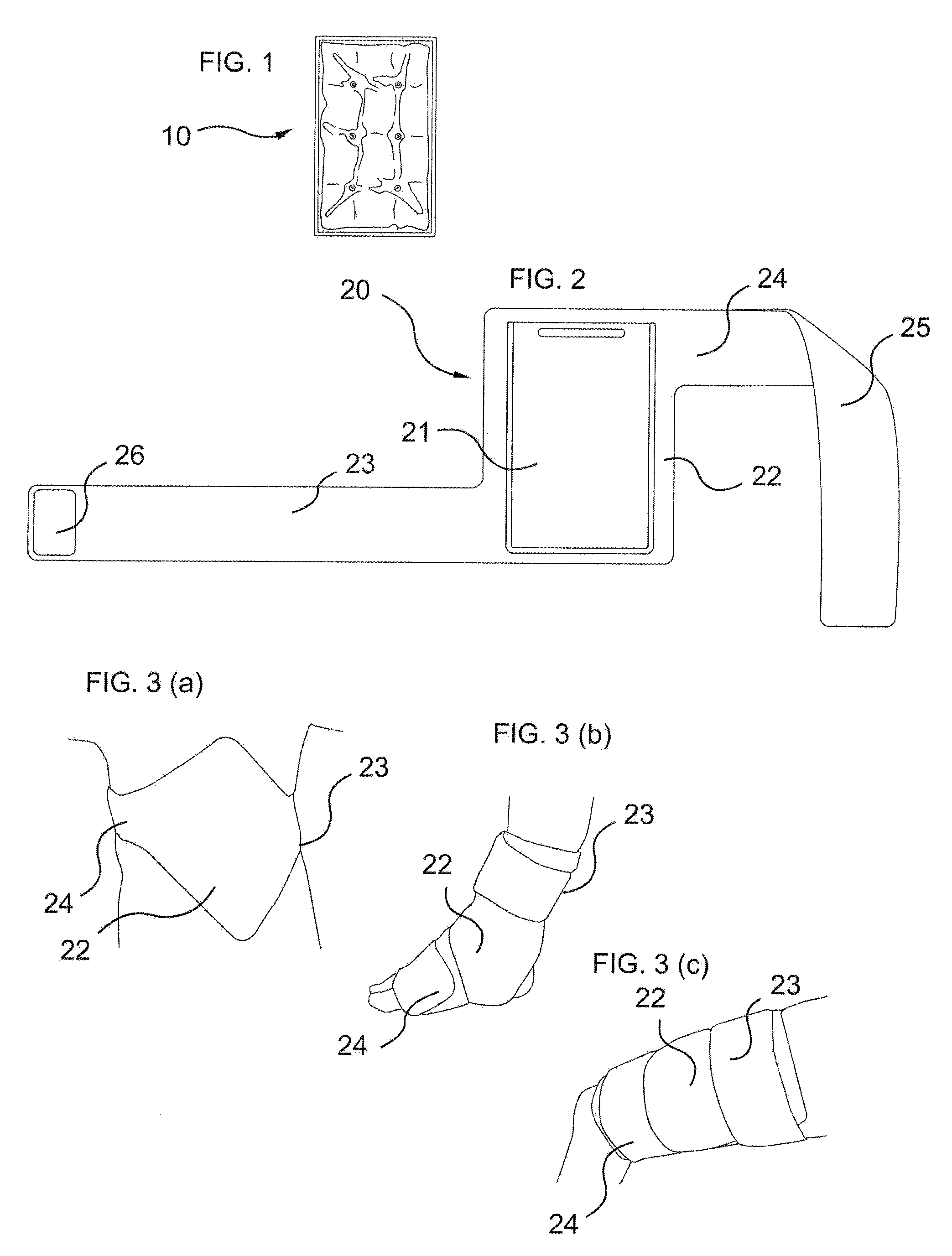
[0041]The panel 22 of the bandage 20 is preferably about 200 mm (8 inches) wide and 270 mm (11 inches) long and made of a resilient material such as a closed-cell neoprene (perhaps laminated) with an outer surface-fastenable covering. The included straps 23 and 24 are preferably about 480 mm long, and extend in opposite parallel directions from opposing diagonal corners of the panel 22, as shown in FIG. 2. The straps need not necessarily be of equal length, and could be anything from 400 mm (16 inches to 850 mm (22 inches) in length. In particular, the combination of a significantly shorter strap with a significantly longer one might be used. This has been found to be advantageous when strapping a person. Both straps have a hook-bearing attachment pad 26 at the end, adapted to removably fasten on to the loop-bearing fabric of the outer surface 25. Because the entire outer surface 25 of the carrier 20 is comprised of the loop-bearing fabric 25, the straps 23 and 24 can be removably f...

example 2

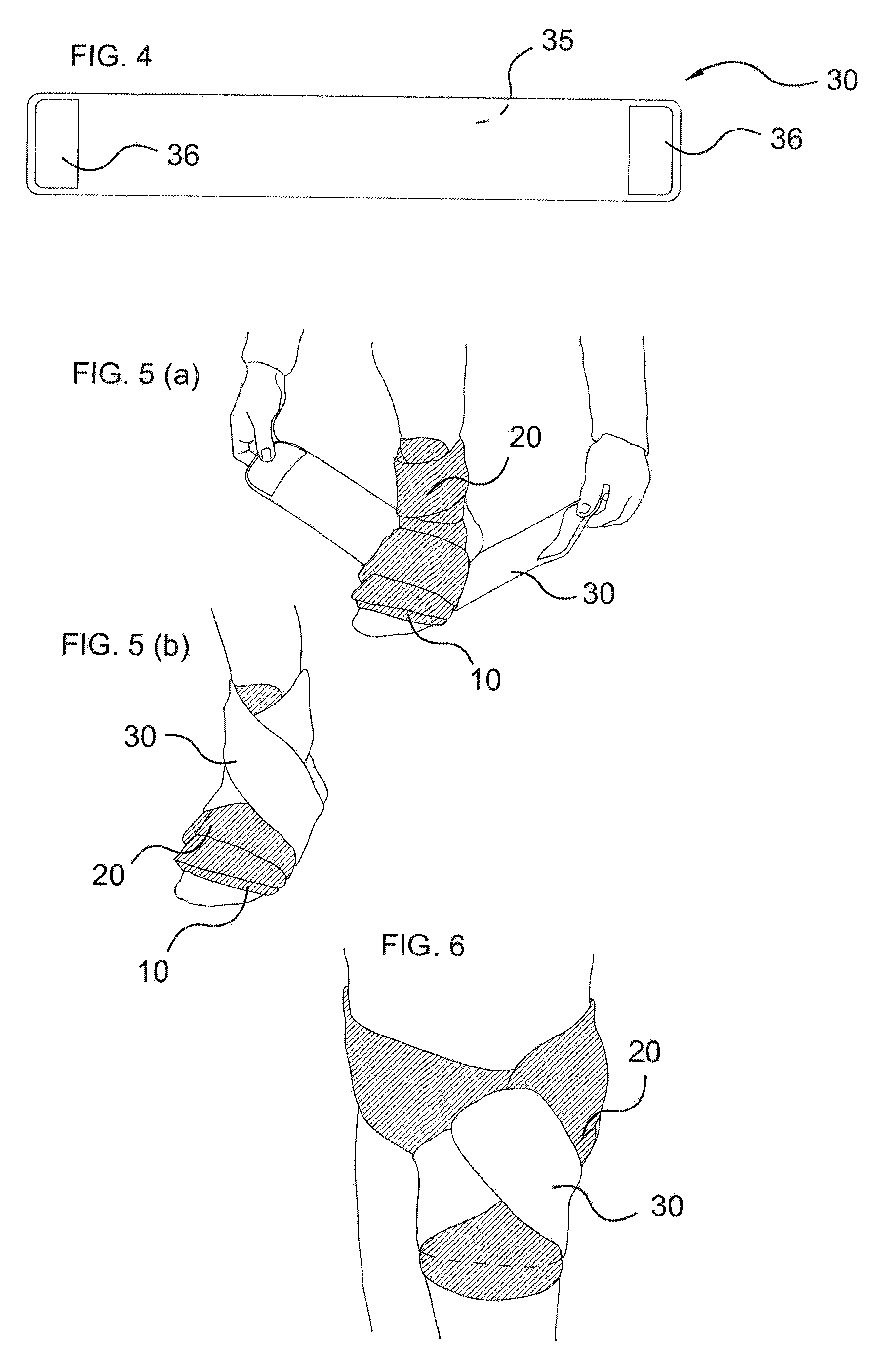
[0048]The preferred embodiment of the invention may be used with a compress 10 as shown in FIG. 1, held in a pocket within the wider area in the middle of the main bandage. The compress employs a mass of fluid gel sealed into a flexible container to apply a temperature. The gel is intended to retain a particular temperature—whether hot or cold—for an extended period, and should therefore comprise a relatively weighty mass. It should also be relatively fluid, so that it can conform to the shape of the body part to which it is applied and enable heat transfer across a wide area of the body surface. The mass may include materials exhibiting a latent heat-related state change. Variants may include or comprise electrically or chemically powered heating means.

[0049]The container may be formed from two sheets of a flexible and tough plastics material such as a vinyl, polypropylene or polyethylene, having a generally rectangular shape and heat-welded together around the edges (12) to provid...


PUM


Abstract

A re-usable bandaging system for treating acute soft-tissue injuries and the like provides protection, support and restraint, and optional heating or cooling and uses straps enabling the system to be placed at one of many sites. A flexible, resilient insulating material, covered with loop-bearing fabric comprises (A) a main bandage that is a rectangular panel with a pocket and (B) two straps at diagonally opposite corners. Each strap has an area of complementary hooks at the free end, to adhere to the bandage when in use. A supplementary bandage (C) is for optional use as a strap when stabilising the main bandage. The system provides a sealed flexible gel pack for heating or cooling an injured part when placed in the pocket. The pack is internally baffled to evenly apply a compress therapy by restriction motion of the contents.

Description

FIELD[0001]This invention relates to the general field of therapeutic equipment for treating bruises, strains, other soft tissue injuries, and weak joints with particular application to means for applying support bandaging with the option of a hot or cold compression to an injured part of the body.BACKGROUND[0002]Injuries sustained during sports and other physical pursuits often involve impact damage to muscle tissues, or strains and sprains resulting from over-stretching or over-turning of connective tissues around joints. With these types of injuries, it is often desirable to reduce swelling and pain in the short term by quickly applying ice or a cold compress to the injured area. Over the longer term, pain from such injuries as well as back, neck or joint pain may be relieved by the application of a hot compress to dilate blood vessels and improve blood flow through the area.[0003]Furthermore, it is often useful to partially or completely immobilise or support the joint or joints...

Claims


Application Information

Patent Timeline
IPC IPC(8): A61L15/00A61F5/00
CPCA61F2007/023A61F5/0111
Inventor LIGHTBOURNE, WARWICK DOUGLAS
Owner CLINICAL TECH N Z
Why Eureka
Try Eureka