
Nozzle insert for a yankee impingement hood

a technology of impingement hood and nozzle insert, which is applied in the direction of drying machines, drying machines with progressive movements, lighting and heating apparatus, etc. it can solve the problems of uneven cross-machine movement and temperature profiles of impinging air, sheet breaks, and profile problems, so as to curtail the swirling of airflow and uniform temperature

Active Publication Date: 2009-01-08
VALMET OY
View PDF5 Cites 1 Cited by
  • Summary
  • Abstract
  • Description
  • Claims
  • Application Information

AI Technical Summary

Benefits of technology

The solution achieves a uniform temperature profile and reduced heat loss, enhancing drying efficiency and product quality by minimizing air transit time and thermal emissions, thus improving the overall drying process.

Problems solved by technology

A problem found in current drying systems involves the uneven cross-machine movement and temperature profiles of the impinging air.
Temperature profile problems can, and often do, originate at the crescent header and nozzle box.
An uneven temperature profile will lead inevitably to a lack of uniformity in the drying process, which can cause sheet breaks and increase production costs and maintenance of the paper-drying machines.

Method used


Image

  • Nozzle insert for a yankee impingement hood
  • Nozzle insert for a yankee impingement hood
  • Nozzle insert for a yankee impingement hood

Examples


Embodiment Construction

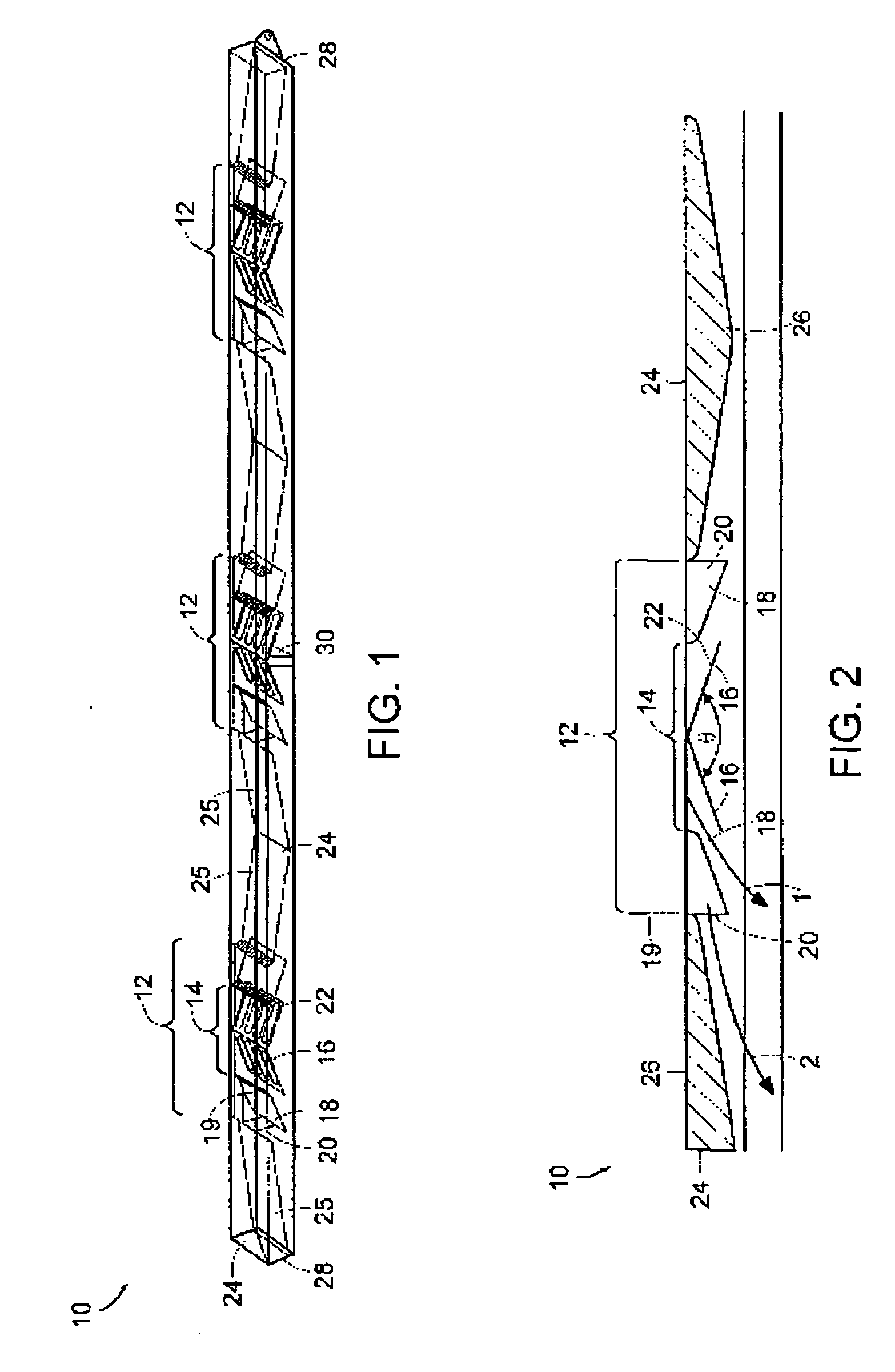
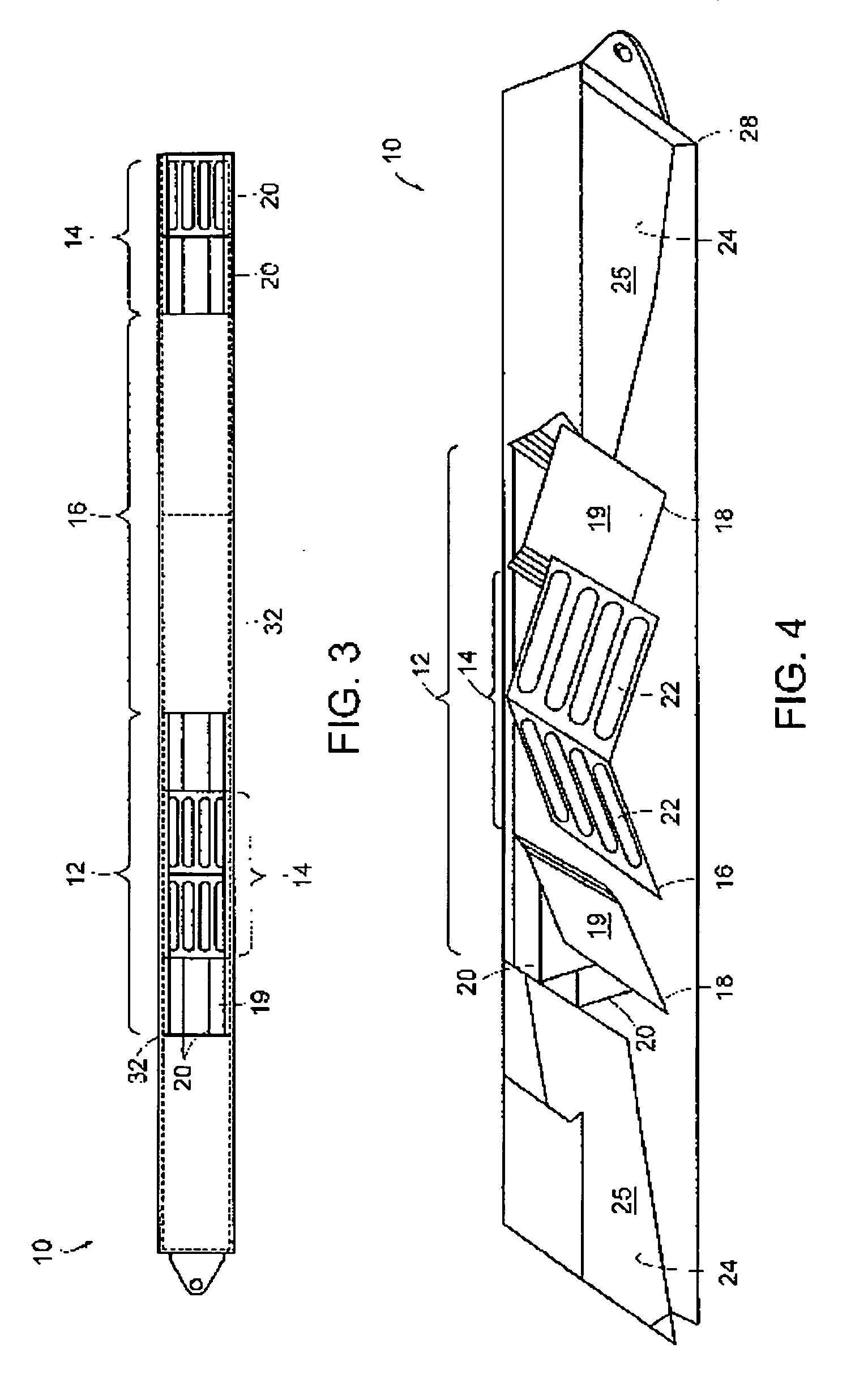
[0020]Referring now to FIGS. 1-4, a nozzle insert 10 is shown in accordance with the present invention shown in various views to more distinctly describe the subject matter of the following claims. The reference numerals refer to the same feature of the nozzle insert 10 throughout each of the Figures.

[0021]The nozzle insert 10 shown in FIG. 1 includes an air intake 12 having a central portion 14 therein. A pair of central vanes 16 is centrally located in the central portion 14. The effect of the central vanes 16 is to direct the air laterally in the general direction of arrow 1 shown in FIG. 2. In one embodiment, the central vanes 16 define a first angle θ that is between 90 and 170 degrees. In a preferred embodiment, the first angle θ is approximately 144 degrees. The central vanes 16 define a plurality of entry ports 22 that permit a limited amount of air to pass directly through the central portion 14 without being laterally diverted. The entry ports 22 are best seen in FIG. 3, w...


PUM


Abstract

The present invention includes a nozzle insert for use in a drying machine of the type used in paper web drying. The nozzle insert of the present invention includes at least one intake having a central portion, wherein a pair of center vanes is disposed for directing airflow. The central portion is bounded by at least one turning vane adapted for directing airflow in a lateral direction. For each turning vane, there is at least one straightening vane adapted for curtailing swirling of the airflow. The vanes are oriented at optimal angles for directing the flow of the nozzle in a lateral direction, while permitting some air to penetrate the central portion through a series of ports. The intakes are bounded by a series of insulated bulkheads, which serve to direct airflow and contain heat-loss through thermal emission.

Description

RELATED APPLICATIONS[0001]The present application is a continuation application that claims priority to U.S. patent application Ser. No. 10 / 995,079 filed on Nov. 22, 2004, the entire content of which is herein incorporated by reference.BACKGROUND OF THE INVENTION[0002]1. Field of the Invention[0003]The present invention relates to the field of paper web drying and in particular to the directing and heating of air in a Yankee Impingement Hood of the type known in the art.[0004]2. Description of the Related Art[0005]A Yankee hood is an air distribution and drying system typically used in the paper industry. A Yankee hood is typically installed over and spaced-apart from a portion of the circumferential surface of a rotatable cylinder. The drying air is heated and pressurized in the system and is then supplied to the Yankee hood dryer where it passes through nozzles at high velocity and impinges on the moving, drying web. The spent air is then collected in the dryer and returned to a r...

Claims


Application Information

Patent Timeline
Patent Type & Authority Applications(United States)
IPC IPC(8): F26B25/00
CPCD21F5/044F26B21/004F26B13/10D21F5/181Y02P70/10
Inventor PARENT, LAURENT ROLANDMORRISON, DAVID SIMPSONYERXA, CRAIG ERNESTCANTOR, RITA ELIZABETHKETCH, DARRELL HERBERT
Owner VALMET OY
Learn More