Wire-forming machine

a wire-forming machine and wire-forming technology, which is applied in the field of wire-forming machines, can solve the problems of high cost, insufficient freedom of programability of time sequence of movements, and slow change of tools, and achieves low cost, low vibration operation of the machine, and low cost.

Active Publication Date: 2009-01-08
WAFIOS AKTIENGES
View PDF5 Cites 10 Cited by
  • Summary
  • Abstract
  • Description
  • Claims
  • Application Information

AI Technical Summary

Benefits of technology

[0026]It is further particularly advantageous if a tool provided as a cutting knife is supported on the machine frame via a supporting arm, instead of on the tool plate, so that the considerable cutting forces are no longer transmitted to the machine frame via the tool plate, its support on the second plate and the support of the second plate, but are introduced directly into the machine frame. This measure, too, contributes to calm, low-vibration operation of the machine according to the invention and to reduced driving forces for both movable plates.
[0027]The wire-forming machine, according to one embodiment of the invention, leads to comparatively low costs and, at the same time, to a considerable cost reduction as compared to many disclosed machines. This improvement is achieved by simplification of the machine and the thus-possible reduction of the number of drive axes, without having to accept greater losses in performance.

Problems solved by technology

However, in this disclosed machine, each tool is provided with its own drive, which makes the machine complex and expensive.
Although, in this case, not every tool unit requires its own, exclusively assigned drive, the time sequence of the movements is not sufficiently freely programmable.
In this disclosed machine, however, the changing of tools is very slow and limits the performance of the machine considerably.
However, there is a disadvantage in that each tool unit has its own drive assigned to it again, which in turn makes the machine expensive, in particular in case of large number of tools.
This allows the wire to be transported to the radially mounted tools; however, this requires movement of very large masses.
However, practical experience has shown that the machine disclosed in JP-P2007-30038A is subject to very strong vibrations during operation and considerable shaking of the entire machine occurs.
The vibrations and shaking leads to highly undesirable vibrations at the respective, already produced, bent-wire parts, thus unfavorably influencing the entire coiling or winding process, respectively.

Method used


Image

  • Wire-forming machine
  • Wire-forming machine
  • Wire-forming machine

Examples


Embodiment Construction

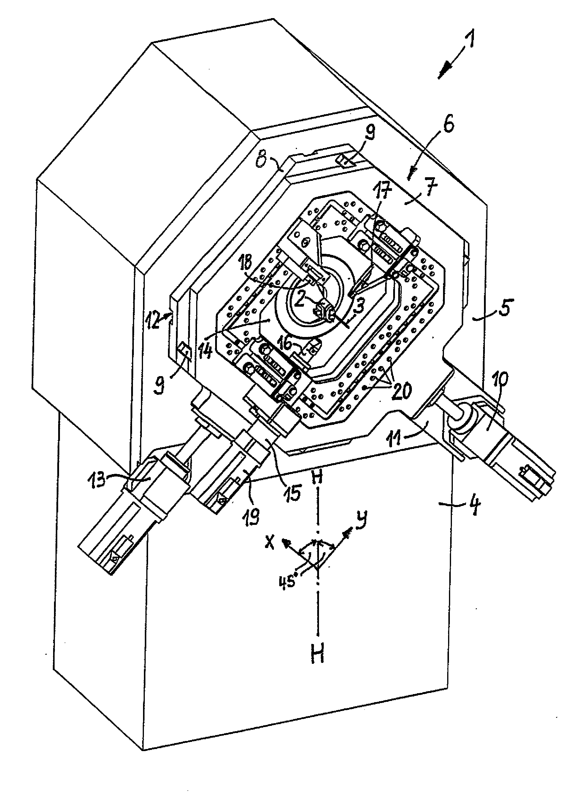
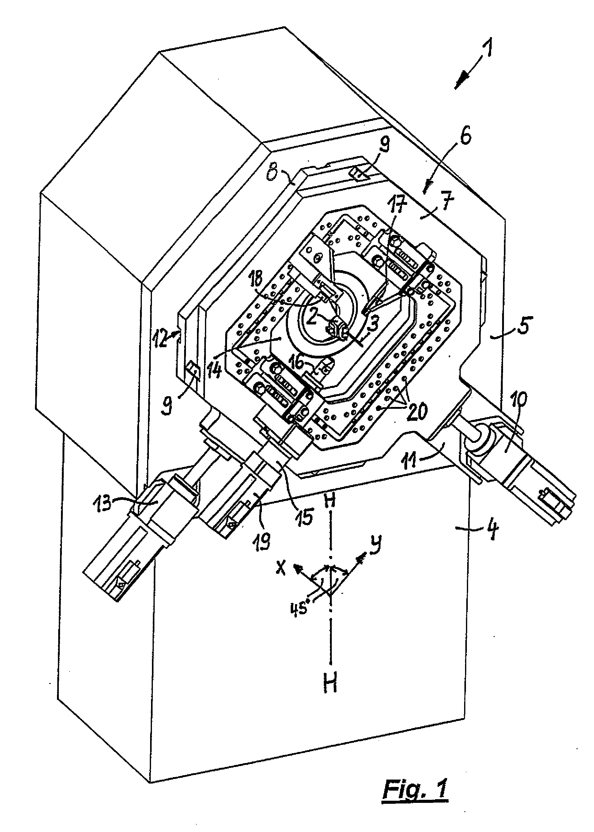
[0034]Referring to FIG. 1, an oblique perspective view from the front (top left) of a wire-forming machine in the form of a leg spring machine 1, which comprises a wire feeder (concealed in the Figure), a straightening unit (not shown) as well as a wire guide 2, is shown. Both the wire feeder and the straightening unit as well as the wire guide 2 are rotatable about the longitudinal axis of the fed wire 3. These modules are known per se: the straightening unit consists of straightening rolls which are mounted in different planes and, by suitable feeding, respectively remove the internal stress within the wire 3 and thus, any bends, or produce a wire whose orientation is as straight as possible. The wire feeder consists of several driven pairs of rolls whose rotation causes the wire 3, clamped between them, to be conveyed through the wire guide 2 into the working area of the machine.

[0035]The leg spring machine I generally comprises a machine frame 4, which is shown only quite basica...


PUM

PropertyMeasurementUnit
angleaaaaaaaaaa
widthaaaaaaaaaa
gap widthaaaaaaaaaa

Abstract

A wire-forming machine, comprising a machine frame, a wire feeder and a wire guide for transporting wire to a working area of the machine where the wire is processed by one or more tools. The tools are affixed on a tool plate on the machine frame and around a recess formed in the plate. A wire is fed through the recess to the working area of the machine. The tool plate is fitted on a second plate and is displaceable along a first direction (x) relative to the second plate, while the second plate is displaceable along a second direction (y) relative to the machine plate. Both directions (x, y) have an inclination of 45° each to the vertical normal axis of the wire-forming machine and are perpendicular to each other.

Description

PRIORITY[0001]The current application claims the benefit of priority to German Patent Application No. 10 2007 031 514.9, filed Jul. 6, 2007, and European Patent Application No. 07 017 890.0, filed on Sep. 12, 2007. Said applications are incorporated in their entirety by reference herein.FIELD OF THE INVENTION[0002]The invention is directed to a wire-forming machine, in particular a spring-bending or spring-winding machine, comprising a machine frame, a wire feeder, a wire guide for transporting the fed wire to a working area of the machine, in which the wire is processed and / or shaped by one or more tools.BACKGROUND OF THE INVENTION[0003]DE 101 34 828 B4 discloses a wire-forming machine in the form of a leg spring machine, wherein a multiplicity of tools are arranged on one plate. Each tool has a base plate and is provided with its own drive assigned only to the particular tool and whose actuation allows the tool to be moved radially towards the wire or away from it. The base plates...

Claims


Application Information

Patent Timeline
Patent Type & Authority Applications(United States)
IPC IPC(8): B21F35/00
CPCB21F1/00B21F35/00B21F3/02B21F1/008
Inventor SPECK, NORBERT
Owner WAFIOS AKTIENGES
Why Eureka
Try Eureka