Pressure Detection Device

a detection device and pressure technology, applied in fluid pressure measurement using inductance variation, variable capacitors, instruments, etc., can solve the problems of limited space where the located devices are used, and the space where the devices are located is limited, so as to achieve efficient use of magnetic field lines, low cost, and easy installation and removal

Inactive Publication Date: 2009-01-08
JMS CO LTD
View PDF15 Cites 12 Cited by
  • Summary
  • Abstract
  • Description
  • Claims
  • Application Information

AI Technical Summary

Benefits of technology

[0021]The pressure detection device according to the present invention can efficiently use magnetic field lines to strongly join a diaphragm to a sensor, while using the magnetic joining method. As a result, the pressure detection device enables the sensor to be easily installed and removed in / from the diaphragm, and can measure a pressure in a wide range. In addition, the pressure detection device according to the present invention that can perform correct pressure detection can be manufactured at a low cost, while reducing a size. Furthermore, the pressure detection device according to the present invention can prevent damage on the diaphragm, thereby detecting a pressure with a high accuracy.
[0022]Accordingly, the present invention is highly suitable for practical use, in recent days the importance of the extracorporeal blood treatments such as dialysis has been increased.

Problems solved by technology

However, a space where the devices are located and a space where the located devices are used are limited.

Method used


Image

  • Pressure Detection Device
  • Pressure Detection Device
  • Pressure Detection Device

Examples


Embodiment Construction

[0047]The following describes a preferred embodiment according to the present invention with reference to the drawings.

[0048]Firstly, an overall structure of the pressure detection device according to the present embodiment is described with reference to FIGS. 1 and 2.

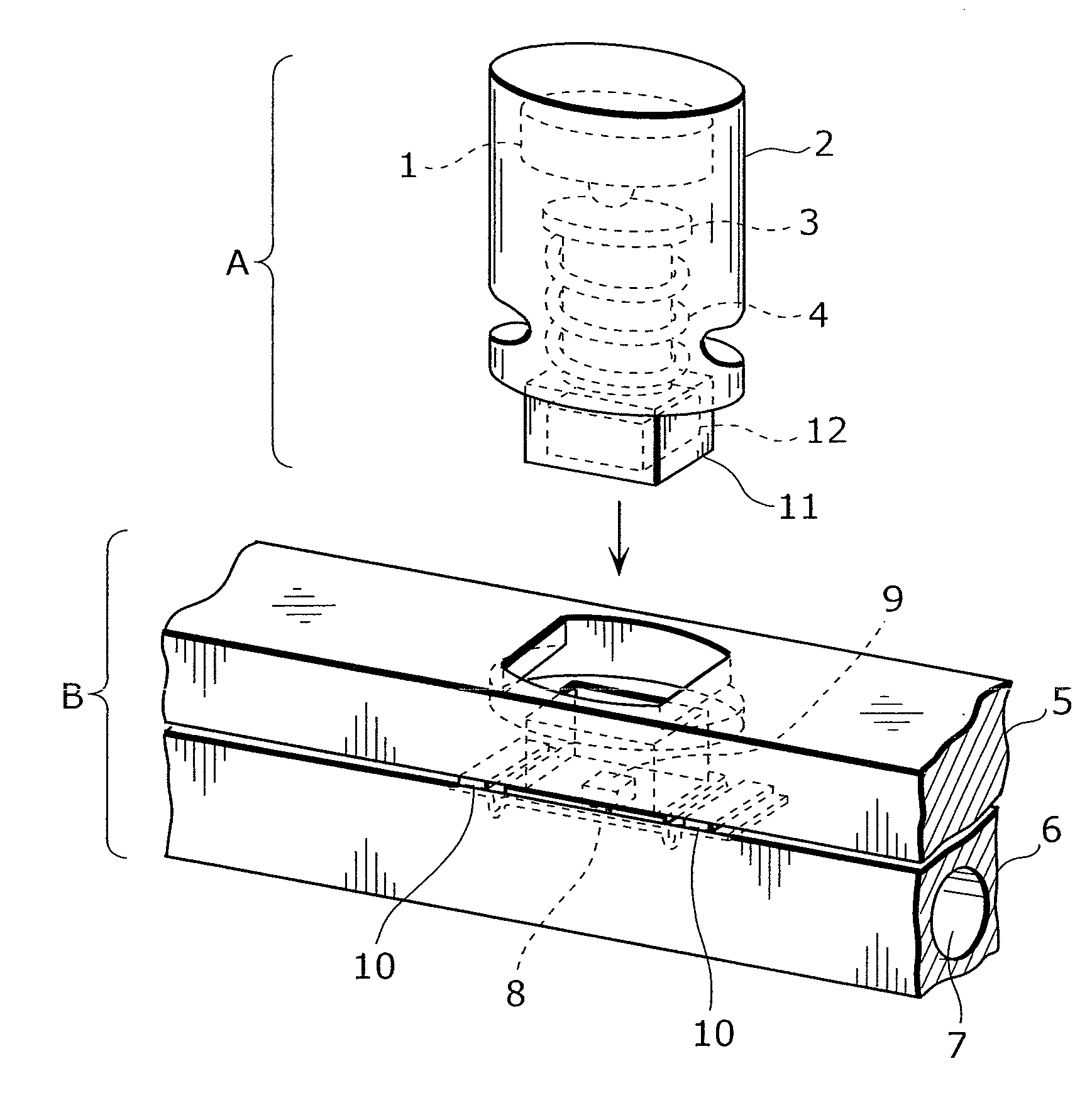
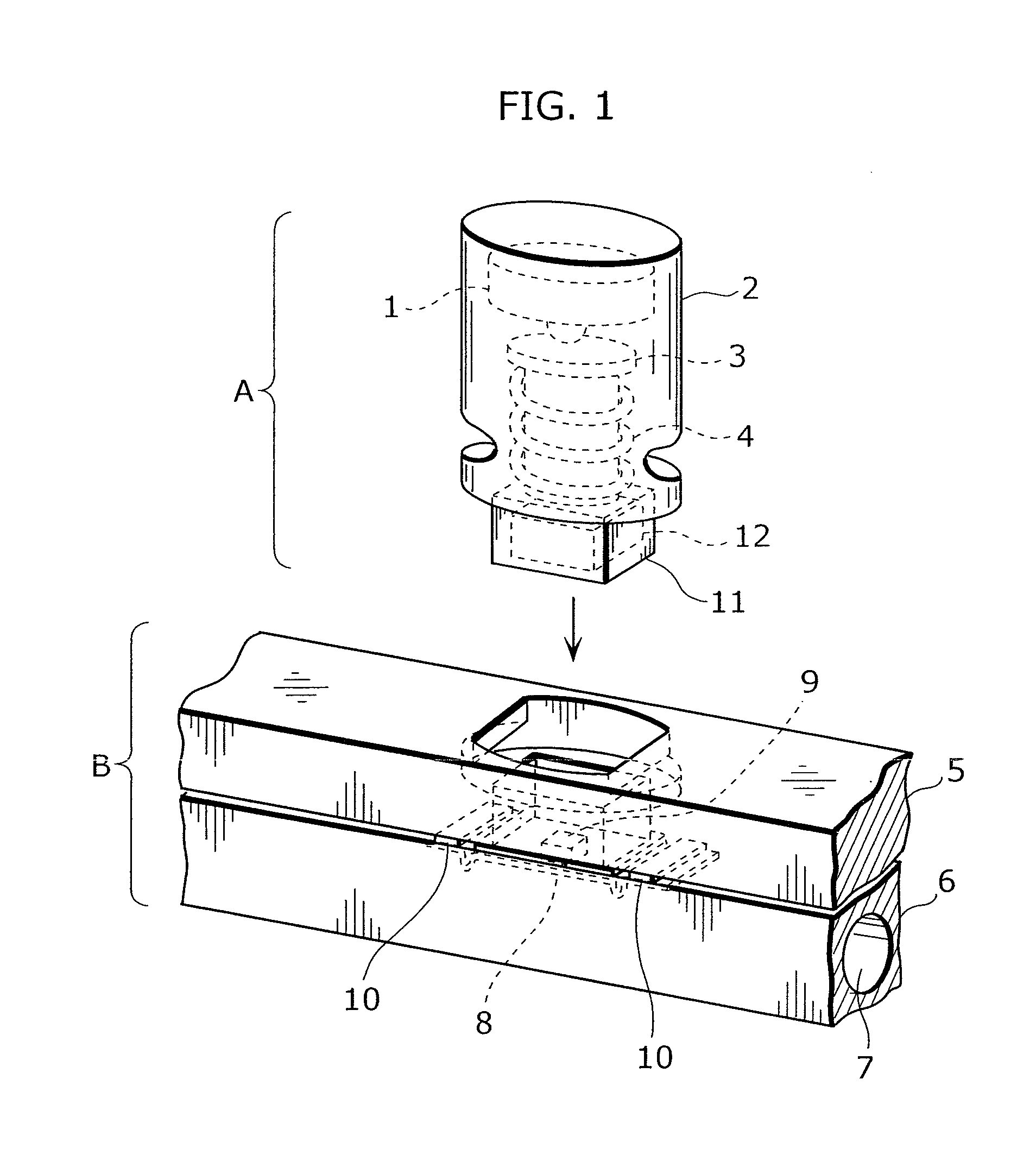
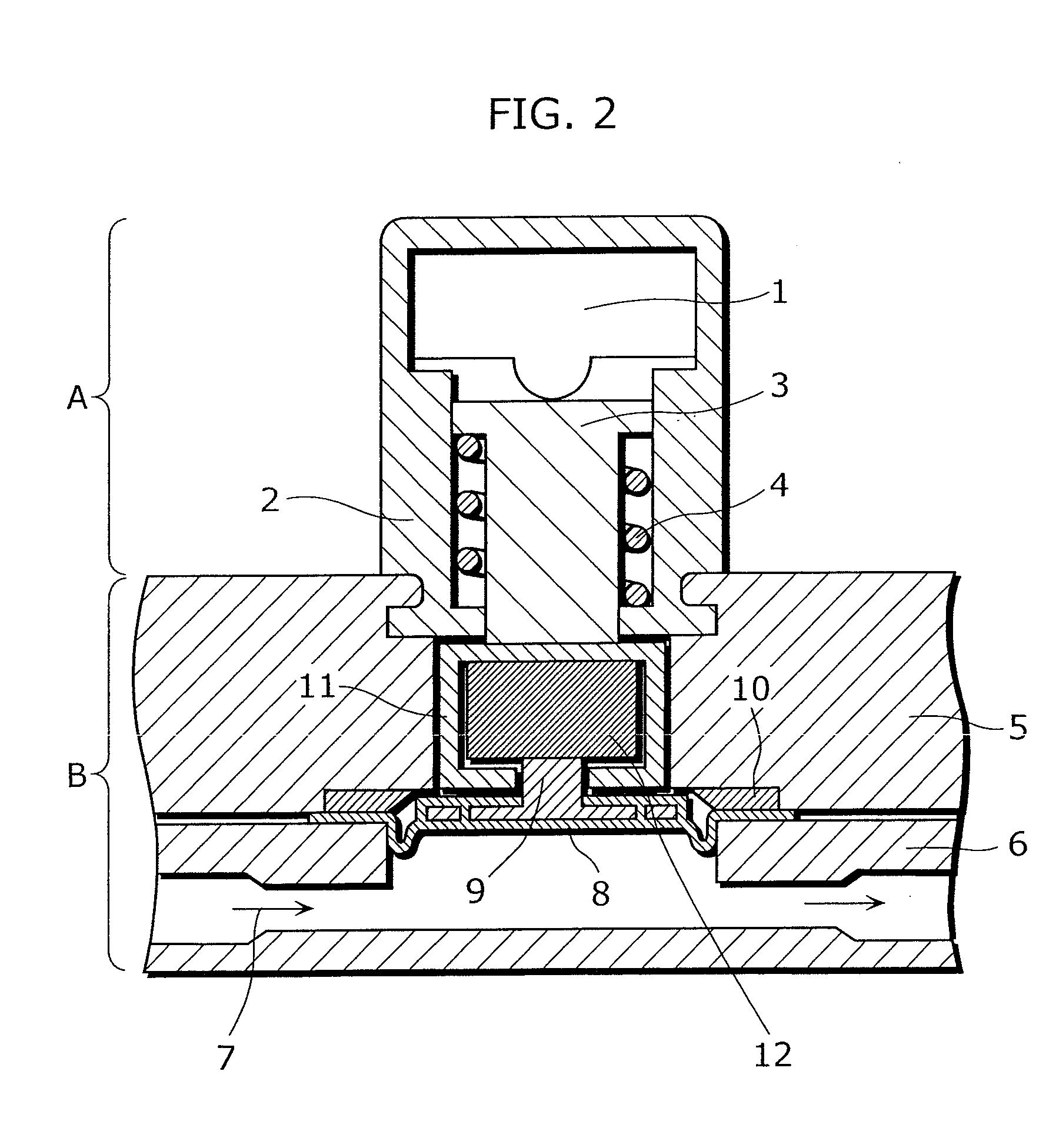
[0049]FIG. 1 is a perspective external view of the pressure detection device according to the present embodiment. FIG. 2 is a cross-sectional view of the pressure detection device according to the present embodiment.

[0050]The pressure detection device according to the present embodiment includes a sensor part A and a disposable part B. The sensor part A is inserted into and engaged with the disposable part B in a direction shown by an arrow in FIG. 1. The sensor part A is a sensor structure that detects a pressure. The sensor part A includes a load cell 1, a sensor chassis 2, a presser 3, a spring 4, a magnet cap 11, and a magnet 12. The disposable part B is a structure included in a blood circuit for which a pressure ...


PUM

PropertyMeasurementUnit
thicknessaaaaaaaaaa
thicknessaaaaaaaaaa
thicknessaaaaaaaaaa

Abstract

Provided is a pressure detection device capable of easy installation and removal of a sensor in/from a diaphragm, measurement of a pressure in a wide rage, and manufacture at a low cost while reducing a size. A sensor part (A) has: a magnet (12) being applied with a load produced by pressing of a diaphragm (8); and a magnet cap (11) covering the magnet (12). The diaphragm (8) has an intra-diaphragm magnetic body (9) buried therein. The intra-diaphragm magnetic body (9) has a protrusion part protruding from the diaphragm (8) so as to be in contact with the magnet (12). The magnet cap (11) has an opening part enabling the protrusion part of the intra-diaphragm magnetic body (9) and the magnet (12) to be joined together.

Description

TECHNICAL FIELD[0001]The present invention relates to a pressure detection device that measures a pressure of a liquid flowing in a tube, without having an air space or a branch tube.BACKGROUND ART[0002]Conventionally, there have been proposed pressure detection devices that measure a pressure of a fluid flowing in a blood circuit used for dialysis, apheresis, Continuous Renal Replacement Therapy (CRRT), or the like, without having a chamber or a branch tube. Extracorporeal circulation of blood in heart surgery, emergency medical care, or the like needs various treatments, thereby increasing the number of circuits and devices. However, a space where the devices are located and a space where the located devices are used are limited. Therefore, such devices for heart surgery, emergency care, and the like which are utilized especially in emergency cases are desired to be easily handled. From this viewpoint, a diaphragm pressure sensor has been disclosed to easily measure a pressure of ...

Claims


Application Information

Patent Timeline
Patent Type & Authority Applications(United States)
IPC IPC(8): G01L9/10
CPCG01L9/007
Inventor KANEKO, MITSURUKITANI, AKI
Owner JMS CO LTD
Why Eureka
Try Eureka