Eureka AIR delivers breakthrough ideas for toughest innovation challenges, trusted by R&D personnel around the world.

Tool organizer insert

a technology for organizing inserts and tools, applied in the field of tool organizer inserts, can solve the problem of not being able to disclose organizer inserts, and achieve the effect of easy cutting to a desired length

Inactive Publication Date: 2009-01-08
NILFERLI BURAK
View PDF26 Cites 13 Cited by
  • Summary
  • Abstract
  • Description
  • Claims
  • Application Information

AI Technical Summary

Benefits of technology

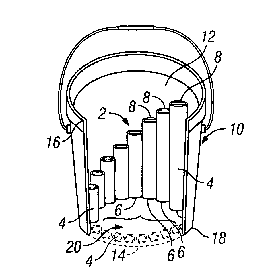
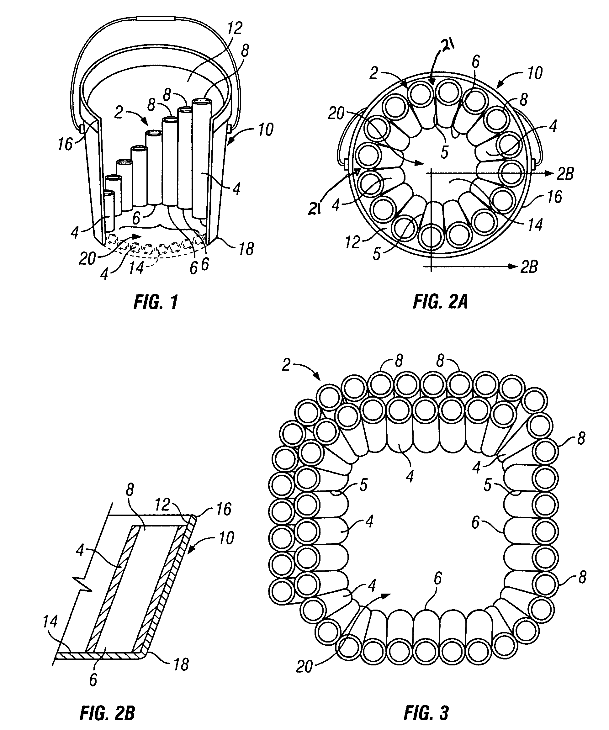
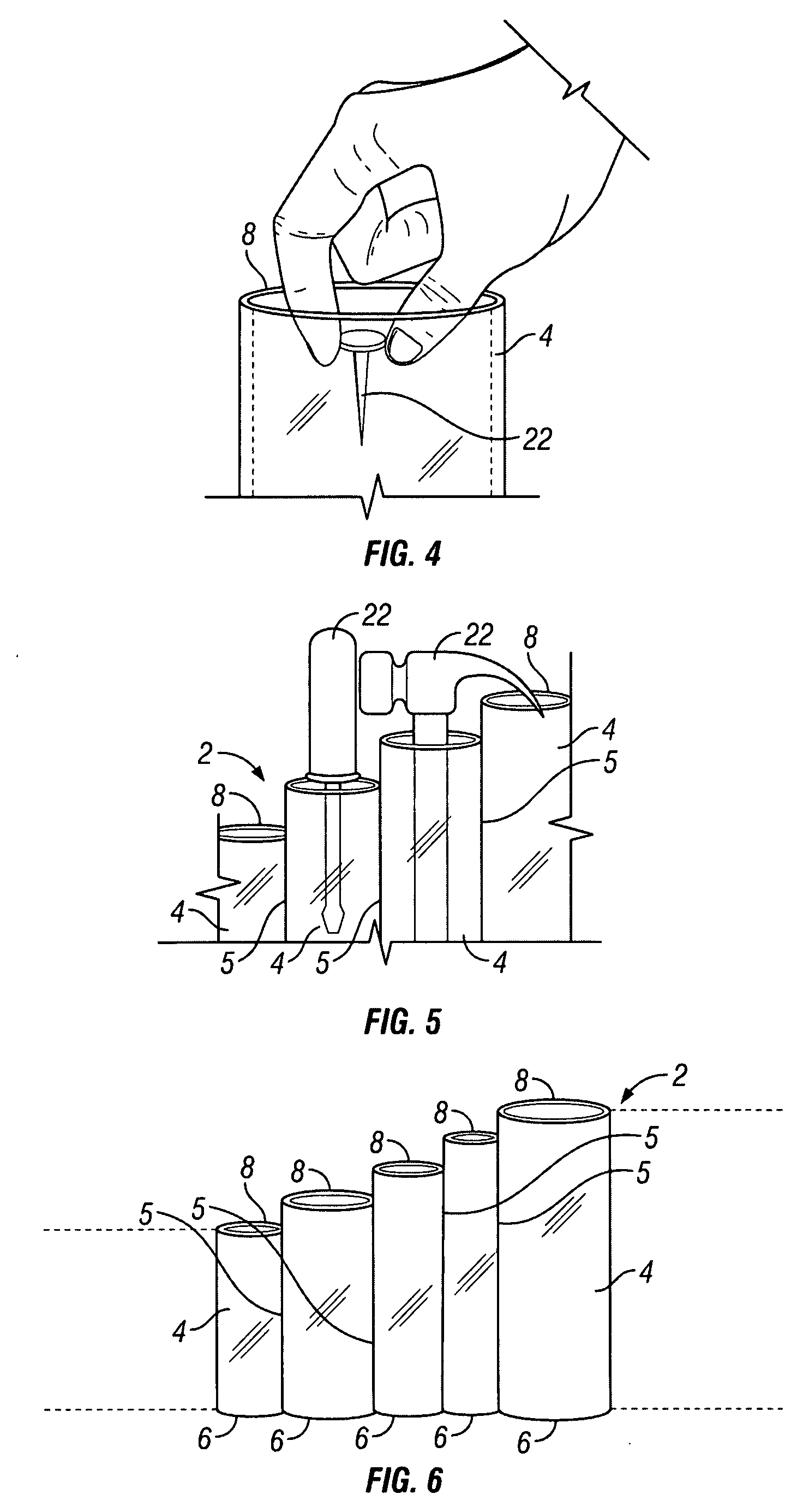
[0019]Using organizer inserts in combination with buckets and similar containers is common practice for a variety of purposes, including tool organization. However, the prior art fails to disclose an organizer insert that is capable of conforming to a wide range of bucket shapes and sizes. The present apparatus solves this problem by providing, in one embodiment, an insert made of a relatively elastic material, allowing some degree of flexibility. The insert comprises a plurality of round tubes joined in side-by-side alignment, and configured with selective diameters and lengths in order to accept a variety of hand tools and other workshop implements. The tubes are round as this shape has been found to have advantages with respect to weight to strength ratio and also provides an ideal shape for storing many elongated tools such as drill bits and such, where a tool held within a round tube is not easily hidden in a corner of the compartment and is easily extracted and replaced from its holder.
[0023]A further objective is to provide a tool organizer insert that maximizes the amount of storage space within the bucket in which it is positioned.
[0025]A further objective is to provide a tool organizer insert that is constructed in such a manner as to be easily cut to a desired length.

Problems solved by technology

However, the prior art fails to disclose an organizer insert that is capable of conforming to a wide range of bucket shapes and sizes.
In addition, the prior art references which disclose organizer inserts for buckets tend to occupy most, if not all, of the bucket's interior volume.

Method used


Image

  • Tool organizer insert
  • Tool organizer insert
  • Tool organizer insert

Examples


Embodiment Construction

[0036]The above described drawing figures illustrate the described apparatus and its method of use in at least one of its preferred, best mode embodiment, which is further defined in detail in the following description. Those having ordinary skill in the art may be able to make alterations and modifications to what is described herein without departing from its spirit and scope. Therefore, it must be understood that what is illustrated is set forth only for the purposes of example and that it should not be taken as a limitation in the scope of the present apparatus and method of use.

[0037]Referring now to FIG. 1, a tool organizer insert 2 is shown mounted in a bucket 10. The insert 2 comprises a plurality of round tubes 4 molded as a unitary part. The tubes 4 are aligned in a side-by-side arrangement with a tube bottom 6 of each one of the tubes 4 terminating in a common plane. In the preferred embodiment, the common plane is defined by an inner floor surface 14 of the bucket 10.

[00...


PUM


Abstract

A tool organizer insert apparatus for a bucket holds tools, equipment, and similar objects within a plurality of round tubes joined in side-by-side alignment. The insert has an outer circumference which frictionally engages the inner wall surface of the bucket, leaving a center area of the bucket unobstructed and available for storage of larger objects not stored within the tubes. In certain embodiments the tubes are molded using a rigid, transparent, thermoplastic material, with each one of the tubes having a selected height and diameter. In another embodiment, the tubes are made of a relatively elastic material, allowing the insert some degree of flexibility in order to conform to containers of various shapes and sizes. In yet another embodiment, the insert and bucket are molded as a single unit.

Description

BACKGROUND OF THE INVENTION[0001]1. Field of the Present Disclosure[0002]This disclosure relates generally to tool organizers, and more particularly, to a tool organizer insert adapted to be inserted into and carried by a bucket, and more particularly to such an insert for integral part of the bucket comprising side-by-side tube structures.[0003]2. Description of Related Art including Information Disclosed Under 37 CFR 1.97 and 1.98[0004]Dickerson, U.S. Pat. No. 2,835,406 discloses a nipple kit consisting of a metal carrying device with slots therein for carrying an assortment of various sized plumbing nipples.[0005]Denholtz, U.S. Pat. No. 4,305,511 discloses a storage device for kitchen utensils, tools, artist supplies, etc. providing annular tiers of storage pockets surrounding a central hollow cylinder whose top contains apertures to support bladed utensils; preferably, the main body of the storage device is a unitary molded plastic structure having spaced double walls between th...

Claims


Application Information

Patent Timeline
Patent Type & Authority Applications(United States)
IPC IPC(8): B25H3/00
CPCB25H3/04
Inventor NILFERLI, BURAKARIN, MUNIR
Owner NILFERLI BURAK
Why Eureka
Eureka Blog
Learn More