
Swivel joint with uniform ball bearing requirements

a technology of ball bearings and swivel joints, which is applied in the direction of adjustable joints, mechanical equipment, rotary machine parts, etc., to achieve the effects of greater axial separation, increased wall thickness, and greater erosion resilien

Active Publication Date: 2009-01-08
SPM OIL & GAS INC
View PDF101 Cites 26 Cited by
  • Summary
  • Abstract
  • Description
  • Claims
  • Application Information

AI Technical Summary

Benefits of technology

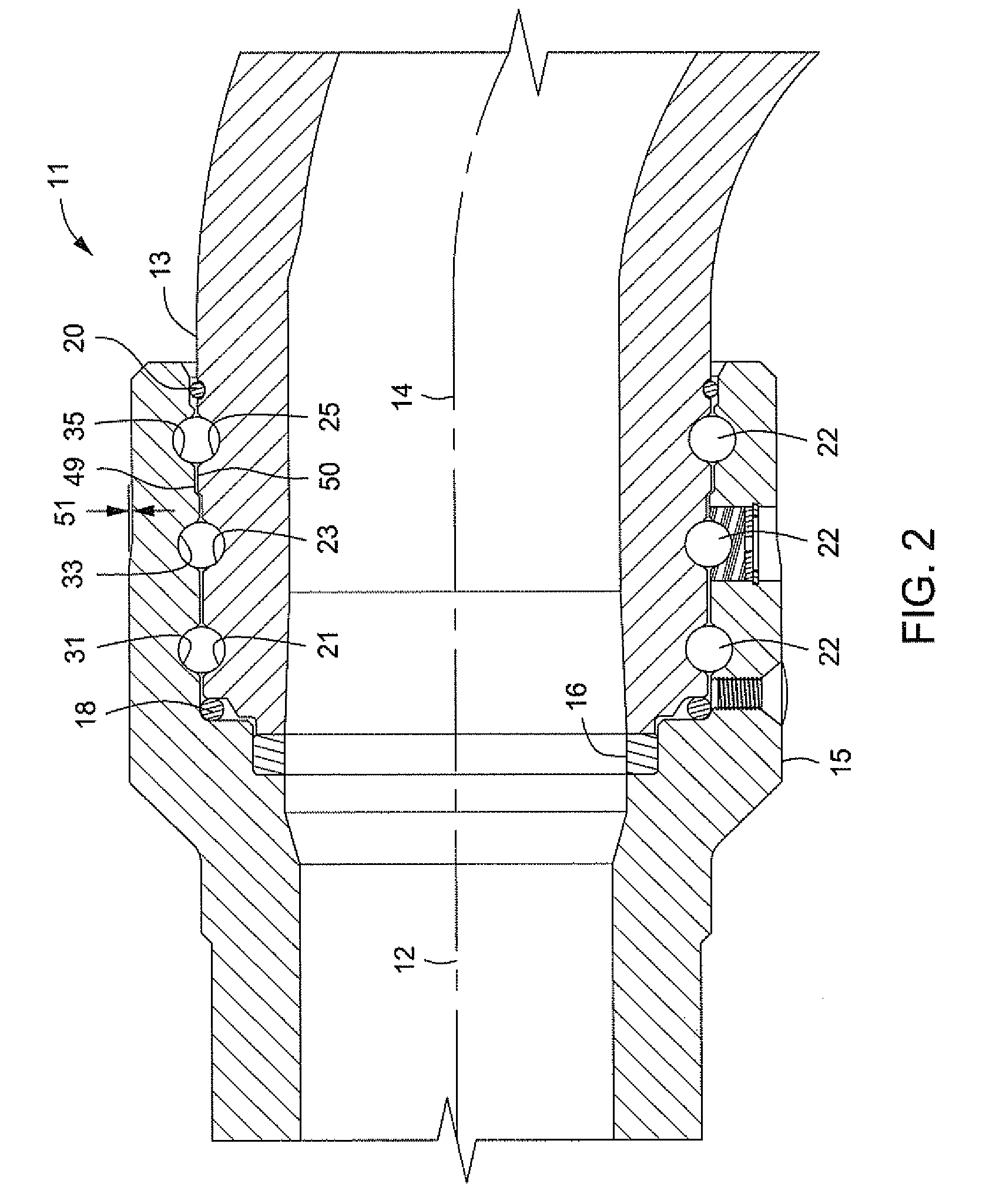
[0007]For example, the main and center male connector bearing races are formed at one diameter, while the third bearing race is formed at a larger diameter. The female races are formed at complementary configurations. In addition to providing diametric and circumferential dimensional changes, this design also provides an increase in wall thickness for greater erosion resilience.
[0008]An increased step in diameter may be formed on the outer diameter of the male connector between the races, with a complementary step in diameter formed on the inner diameter of the female connector between its races. This design results in more support around the main ball races that are closest to the seal ring. This configuration also produces more even distribution of loads and stresses throughout all of the ball races, and provides extended life of the ball races.
[0009]One embodiment of the invention also is provided with greater axial separation between the various sets of ball races compared to conventional designs. For example, the axial distance between each set of races is increased. This wider stance between ball races results in a more stable ball race assembly and provides better ball race loading and longer ball race life.

Problems solved by technology

Swivel joints are required to perform under extreme conditions, such as handling fluids that contain abrasives that cause erosion of the joint components, high pressures, and extreme temperatures.

Method used


Image

  • Swivel joint with uniform ball bearing requirements
  • Swivel joint with uniform ball bearing requirements
  • Swivel joint with uniform ball bearing requirements

Examples


Embodiment Construction

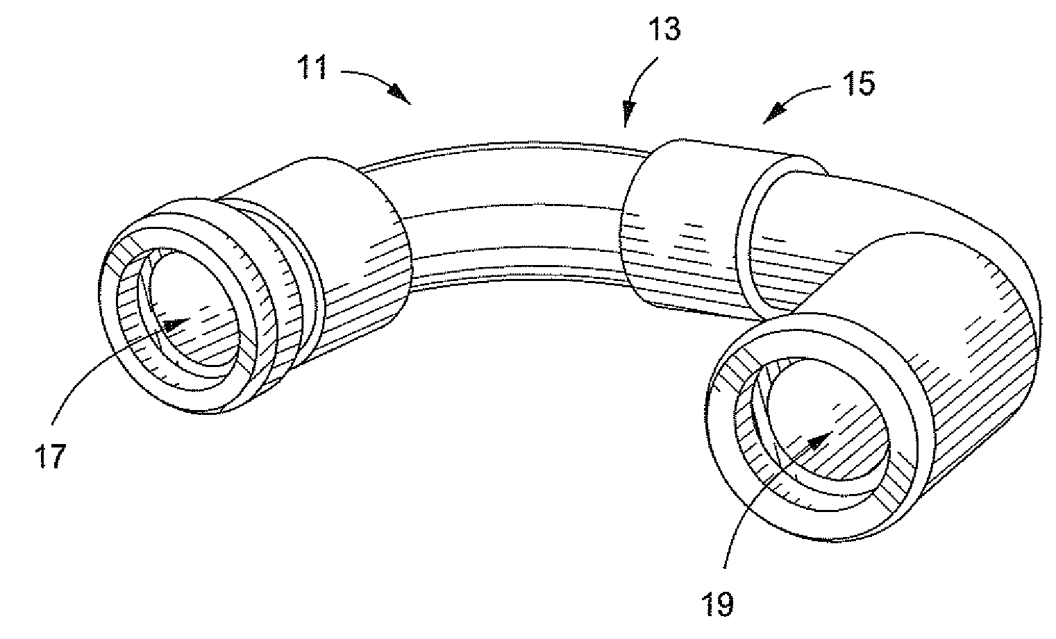
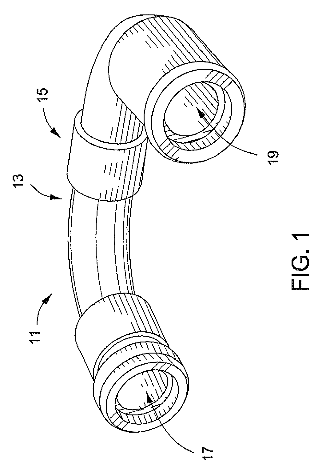
[0018]Referring to FIGS. 1-6, embodiments of a system, method, and apparatus for swivel joints having uniform ball bearing requirements for all bearing races are disclosed. As shown in FIGS. 1 and 2, one type of swivel joint 11 comprises a male connector 13 and a female connector 15 that coaxially interconnect along central axes 12, 14 thereof. The swivel joint 11 also includes connectors 17, 19 for connecting the swivel joint to other well service components (not shown). The swivel joint permits the male and female connectors 13, 15 to swivel about the axes 12, 14 relative to each other while still maintaining a high pressure seal therebetween.

[0019]FIGS. 3 and 4 depict enlarged sectional views of one embodiment of male and female connectors 13, 15, respectively, such as for 3-inch diameter components rated at a working pressure of 15,000 psi. A main seal ring 16 (FIG. 2) for the swivel joint 11 is located between distal end 17 (FIG. 3) of male connector 13, and proximal end 19 (FI...


PUM


Abstract

A swivel joint has uniform ball bearing requirements for all bearing races. The swivel joint has a male connector and a female connector that coaxially interconnect and swivel relative to each other while still maintaining a high pressure seal. Each connector has three bearing races to form three sets of bearing races, each of which supports the same number of ball bearings. The circumference of the main set of races are enlarged by less than the diameter of one ball, so it is impossible to add another ball to the coupled male and female connectors of the swivel joint.

Description

[0001]This application claims priority to and the benefit of U.S. Provisional Patent Application No. 60 / 947,738, filed Jul. 3, 2007, which is incorporated herein by referenceBACKGROUND OF THE INVENTION[0002]1. Technical Field[0003]The present invention relates in general to swivels joints for high pressure well service applications and, in particular, to an improved system, method, and apparatus for swivel joints having uniform ball bearing requirements for all bearing races.[0004]2. Description of Related Art[0005]High pressure well service applications require the use of swivel joints to interconnect various plumbing configurations. A swivel joint has male and female connectors that are joined and sealed, but which permit swivel action between them. Circumferential bearing seats are formed in the male and female connectors to capture ball bearings therebetween to facilitate the swiveling action. Swivel joints are required to perform under extreme conditions, such as handling fluid...

Claims


Application Information

Patent Timeline
Patent Type & Authority Applications(United States)
IPC IPC(8): F16L27/00
CPCF16C19/08F16C43/06F16C2361/00F16L27/0828F16L27/0845F16C2240/84
Inventor MATZNER, MARK D.WITKOWSKI, BRIAN C.
Owner SPM OIL & GAS INC
Learn More