Magnetic sensing device and electronic compass using the same

Inactive Publication Date: 2009-01-08
ALPS ALPINE CO LTD
View PDF1 Cites 36 Cited by
  • Summary
  • Abstract
  • Description
  • Claims
  • Application Information

AI Technical Summary

Benefits of technology

[0017]According to the configuration described above, even when a leakage magnetic field acts on the magnetic sensors, a peak of a voltage-versus-magnetic-field characteristic curve of the magnetic sensors can be detected. As a result, even in an environment in which a leakag

Problems solved by technology

For example, there is a problem that, when an electronic compass in which the above-described magnetic sensing circuit is used is mounted in a mobile phone or the like, it is difficult to accurately detect an external magnetic field because the electronic co

Method used


Image

  • Magnetic sensing device and electronic compass using the same
  • Magnetic sensing device and electronic compass using the same
  • Magnetic sensing device and electronic compass using the same

Examples


Embodiment Construction

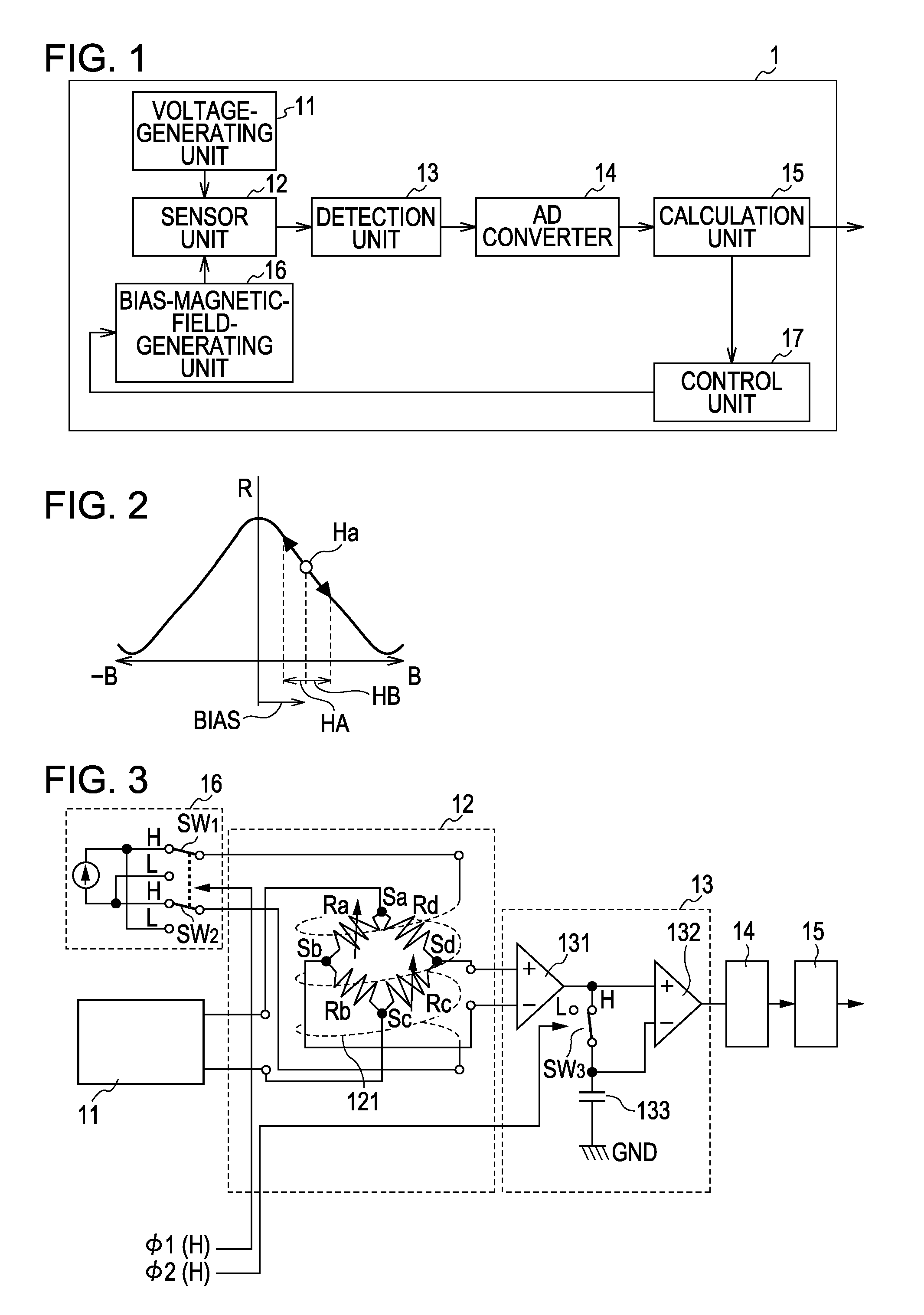
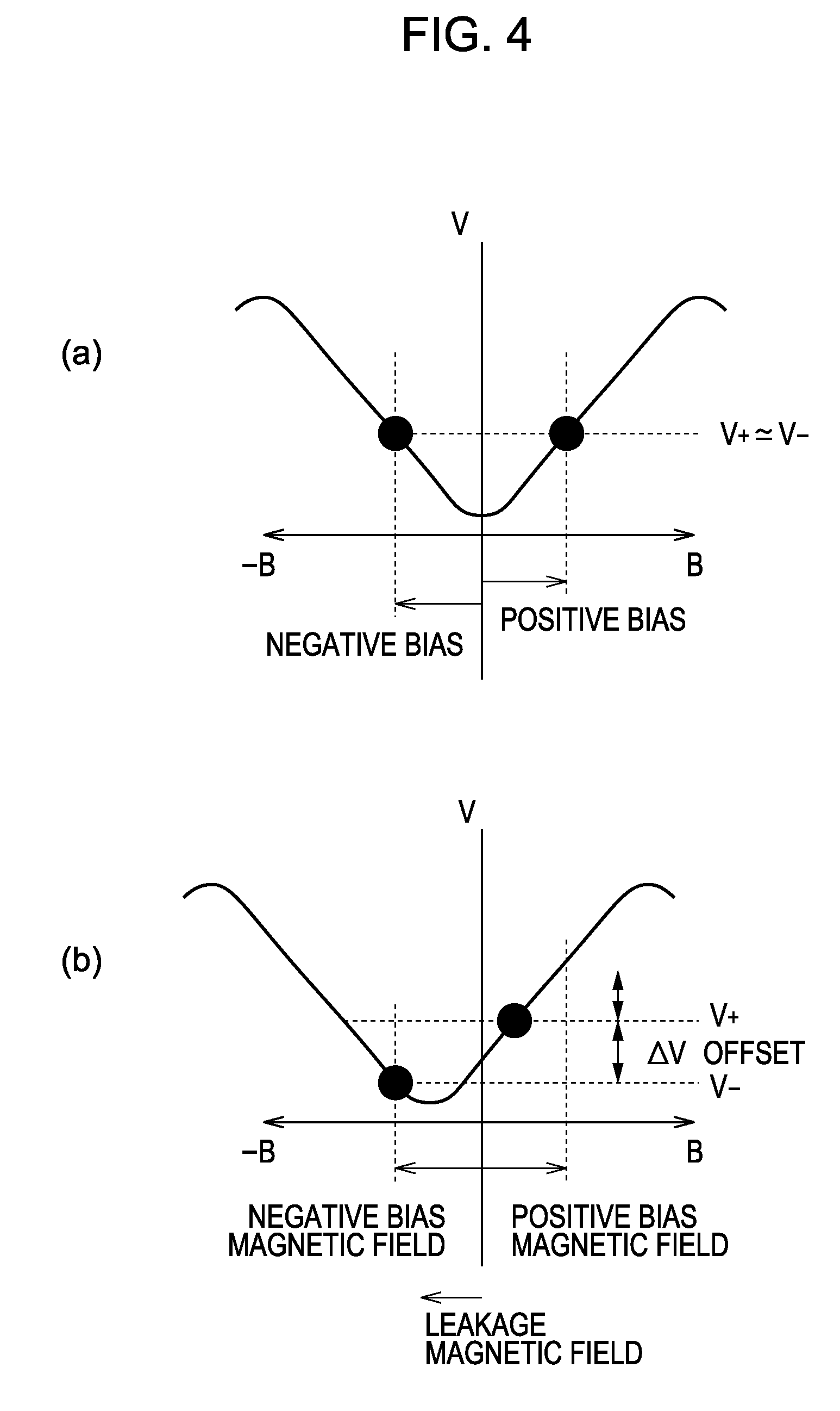
[0026]The present inventor has taken notice of the following things: a magnetoresistive element that shows a symmetrical change in resistance with respect to a magnetic field is used in a magnetic sensor; and, in such a case, when a peak of the characteristic curve of the magnetoresistive element is broad, it is difficult to perform accurate detection of magnetism in the existence of a leakage magnetic field. Then, the present inventor has found that bias magnetic fields are controlled so that the difference between output voltages obtained by applying the positive and negative magnetic fields becomes substantially zero, thereby performing accurate detection of magnetism. Thus, the present inventor has made the present invention.

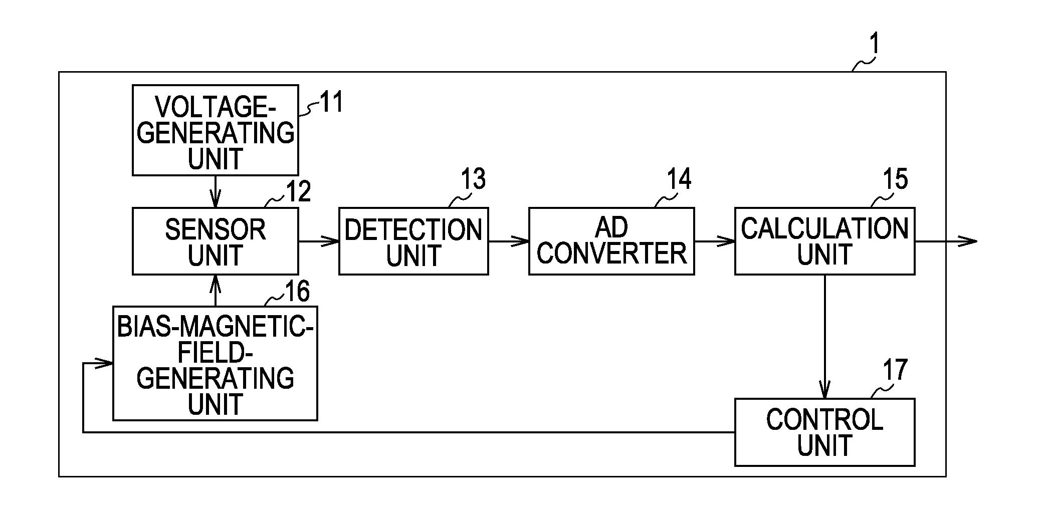
[0027]The gist of the present invention is as follows: there is provided a magnetic sensing device including a magnetic sensor for detecting magnetism, bias-magnetic-field generating means for applying bias magnetic fields having opposite polarities to each ...


PUM


Abstract

Positive and negative bias magnetic fields are applied to a sensor unit 12 to determine first and second output voltages. A first difference between the first and second output voltages is calculated. Next, correction bias magnetic fields, each of which is obtained by adding an additional bias magnetic field to a corresponding one of the positive and negative bias magnetic fields, are applied to the sensor unit 12 to determine first and second output voltages. A second difference between the first and second output voltages is calculated. Then, the first difference is compared with the second difference. When the first difference is larger than the second difference, the magnitude of the additional bias magnetic field is increased to minimize the difference, i.e., to made the difference substantially zero.

Description

CLAIM OF PRIORITY[0001]This is a continuation of International Application No. PCT / JP2007 / 053575, filed Feb. 27, 2007, which is incorporated herein by reference in its entirety.BACKGROUND OF THE INVENTION[0002]1. Field of the Invention[0003]The present invention relates to a magnetic sensing device and an electronic compass using the magnetic sensing device.[0004]2. Description of the Related Art[0005]When direction determination is electronically performed, a magnetic sensor for detecting an external magnetic field such as a geomagnetic field is used. When a direction is determined using a magnetic sensing circuit including the magnetic sensor, a technique is known, in which an alternating-current magnetic field is applied to the magnetic sensor, and in which a voltage that is output from the magnetic sensor when the alternating-current magnetic field is applied is used.[0006]In this technique, a magnetic sensor is used, which includes a magnetoresistive element that changes an int...

Claims


Application Information

Patent Timeline
IPC IPC(8): G01R33/02
CPCG01R33/0023G01R33/091G01R33/09G01R33/0029
Inventor YAMADA, YUKIMITSU
Owner ALPS ALPINE CO LTD
Why Eureka
Try Eureka