Steam generator dual head sludge lance and process lancing system

a technology of sludge lance and steam generator, which is applied in the direction of nuclear elements, flush cleaning, cleaning using liquids, etc., can solve the problems of tube cracking, tube thinning, and tube leakag

Active Publication Date: 2009-01-08
WESTINGHOUSE ELECTRIC CORP
View PDF16 Cites 27 Cited by
  • Summary
  • Abstract
  • Description
  • Claims
  • Application Information

AI Technical Summary

Benefits of technology

[0012]1) opening at least one handhole; 2) introducing a moveable sludge lance having dual lance heads separated by a distance greater than the diameter of the central stay rod; and 3) sludge lancing the hot leg side and the cold leg side of the tube bundle with the moveable sludge lance, so that the dual lance heads traverse the central tube lane to extend beyond the central stay rod allowing continuous and complete lancing of the hot and cold sides of the tube bundle.

Problems solved by technology

High caustic levels found in the vicinity of the cracks in tube specimens taken from operating steam generators and the similarity of these cracks to failures produced by caustic under controlled laboratory conditions, have identified high caustic levels as the possible cause of the intergranular corrosion, and thus the possible cause of the tube cracking.
The other cause of tube leaks is thought to be tube thinning.
In all the above apparatus, the single head used must stop at a central rod in the tube sheet, so that the central row of tubes across the tube lane and the hot and cold leg is difficult to clean, and that central row of tubes also crosses the middle of the “kidney” region of the hot leg.

Method used


Image

  • Steam generator dual head sludge lance and process lancing system
  • Steam generator dual head sludge lance and process lancing system
  • Steam generator dual head sludge lance and process lancing system

Examples


Embodiment Construction

[0021]In a U-tube type steam generator, a tube sheet supports a bundle of heat transfer U-tubes. During operation, sludge forms on the tube sheet around the U-tubes and in the annulus between the U-tubes and the tube sheet, causing potential failure of the tubes. Failure of the tubes may result in a release of radioactive particles from the primary reactor coolant into the feedwater of the steam generator. The invention, herein described, is a method for removing this sludge accumulation before it causes tube failure.

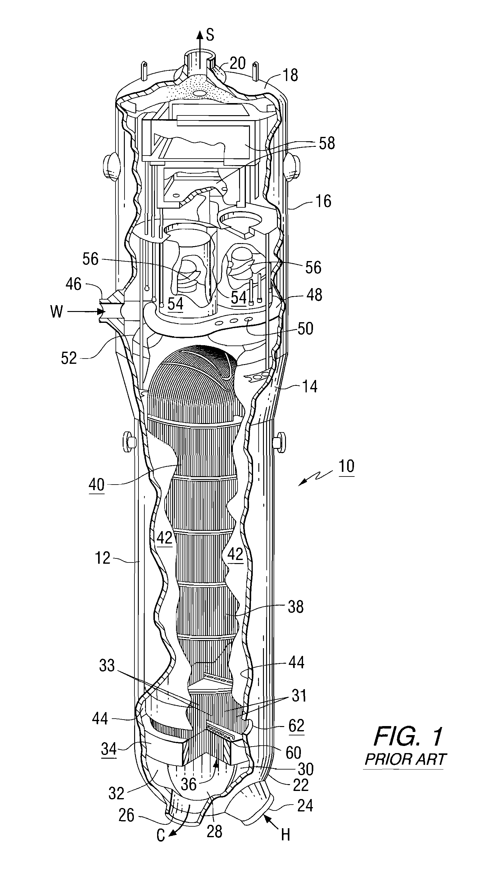
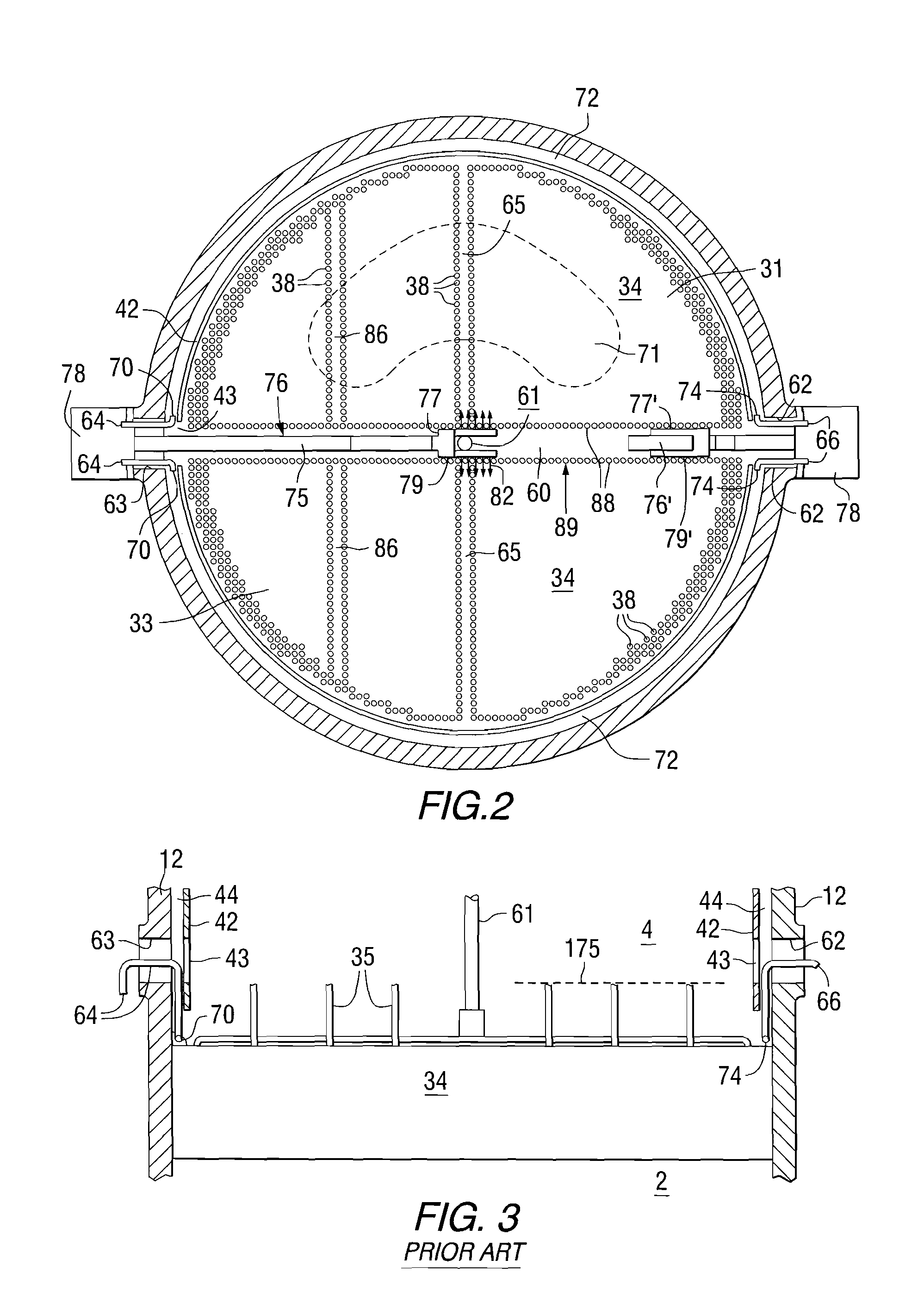
[0022]Referring to FIG. 1, prior art nuclear steam generators includes a primary side 2 and a secondary side 4 among the tube bundle 40 (best shown in FIG. 3), hydraulically isolated from one another by a tubesheet 34. The nuclear steam generator referred to generally as 10, comprises a lower shell 12 connected to a frustoconical transition shell 14 which connects lower shell 12 to an upper shell 16. A dished head 18 having a steam nozzle 20 disposed thereon encloses up...


PUM


Abstract

A method of cleaning sludge from the tube sheet (34) of a nuclear steam generator (10) includes introducing a moveable sludge lance (76) said moveable sludge lance having duel lance heads (77) through handholes (62) in the side of the generator and into a central tube lane (60) having a central stay rod (61) and sludge lancing with high pressure fluid through the row 1 tubes (85) in the tube lane, where the distance (200) between the dual lance heads (77) is wide enough to allow the dual lance heads to extend beyond the central stay rod (61).

Description

CROSS-REFERENCE TO RELATED APPLICATION[0001]This application claims the benefit of U.S. Provisional Patent Application Ser. No. 60 / 947,775, filed Jul. 3, 2007.FIELD OF THE INVENTION[0002]This invention relates to steam generators and more particularly to methods for removing sludge deposits from the tubesheets of steam generators, particularly nuclear steam generators using a dual head sudge lance that can bypass and extend beyond the central rod of the tube sheet support.BACKGROUND OF THE INVENTION[0003]A typical nuclear steam generator comprises a vertically-oriented shell, a plurality of U-shaped tubes disposed in the shell so as to form a tube bundle, a tube-sheet for supporting the tubes at the ends opposite the U-like curvature, a dividing plate that cooperates with the tubesheet forming a primary fluid inlet plenum at the one end of the tube bundle and a primary fluid outlet plenum at the other end of the tube bundle. A primary fluid inlet nozzle is in fluid communication wit...

Claims


Application Information

Patent Timeline
Patent Type & Authority Applications(United States)
IPC IPC(8): F22B37/48F28G7/00
CPCF28G1/166F28G15/04F22B37/486
Inventor HABERMAN, ERIC R.
Owner WESTINGHOUSE ELECTRIC CORP
Why Eureka
Try Eureka