Image processing apparatus and image processing method

Active Publication Date: 2009-01-08
FUJIFILM CORP
View PDF2 Cites 13 Cited by
  • Summary
  • Abstract
  • Description
  • Claims
  • Application Information

AI Technical Summary

Benefits of technology

[0023]Thereby, the user can easily display the region which the user desires to observe at the optimal viewpoint and in the sight line direction without performing a complicated operation by only selecting the bone region which the

Problems solved by technology

However, the method described in the above described Patent Document has the problem that the method is very complicated because a number of operations are required until a desired vie

Method used


Image

  • Image processing apparatus and image processing method
  • Image processing apparatus and image processing method
  • Image processing apparatus and image processing method

Examples


Embodiment Construction

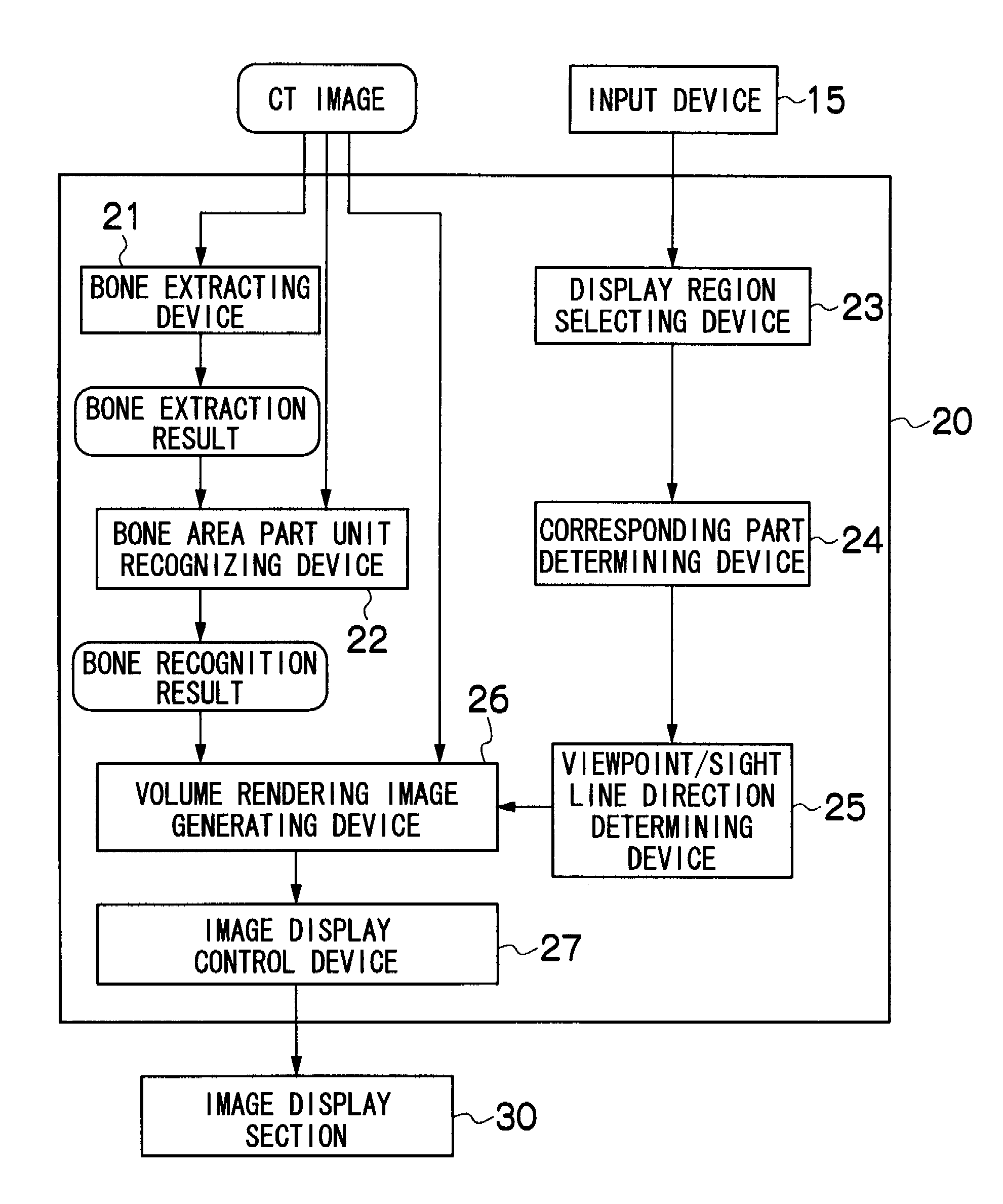
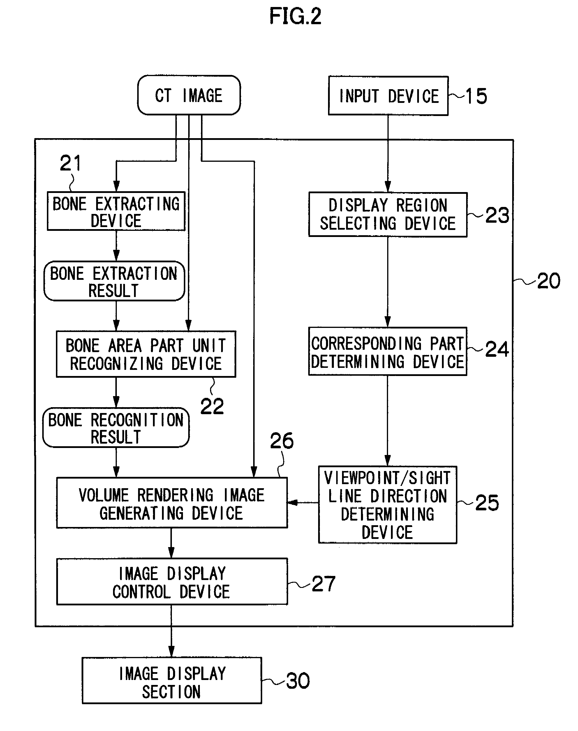
[0037]Hereinafter, an image processing apparatus and an image processing method according to the present invention will be described in detail with reference to the attached drawings. In the present invention, a user only designates the region which the user desires to observe, whereby the viewpoint and the sight line direction optimal for observation of the region are automatically determined, and the three-dimensional image seen in the sight line direction from the viewpoint is generated to be displayed.

[0038]As one embodiment of the present invention, the case where a user observes a certain bone region in a skeleton area will be described as an example. In the following embodiment, as a medical image, a CT image will be especially described as an example, but the present invention is not limited to the CT image, but can be also applied to a slice image with a plurality of images stacked in layer. Further, what is called a slice image in the present embodiment is also called a se...


PUM


Abstract

An image processing apparatus characterized by including a device which recognizes, in a bone part unit, a bone area extracted from a medical image and including a bone region constituted of several bone parts, a device which is used to select the bone region to be displayed, a device which is used to determine the bone parts corresponding to the selected bone region, a device which is used to determine a viewpoint and a sight line direction for observing the selected bone region, a device which generates a volume rendering image which displays the bone area with the viewpoint and the sight line direction, based on the bone area of the medical image recognized in the bone part unit, and the determined viewpoint and sight line direction, and a device which is used to conduct control to display the generated volume rendering image.

Description

BACKGROUND OF THE INVENTION[0001]1. Field of the Invention[0002]The present invention relates to an image processing apparatus and an image processing method, and particularly relates to an image processing apparatus and an image processing method for displaying an image with an optimal viewpoint and sight line direction by using a bone part unit corresponding to a designated bone region from a bone area extracted from an X-ray CT image in a medical image.[0003]2. Description of the Related Art[0004]Conventionally, medical diagnosis is widely performed by using the sectional images of the insides of human bodies of CT, MRI, PET and the like, and an image diagnosis support system using a computer is known.[0005]At this time, as the preprocessing of MIP (maximum intensity projection) image display, bone number recognition, or bone display in the image diagnosis support system, a bone area is automatically extracted from an X-way CT image.[0006]When it is confirmed whether the result o...

Claims


Application Information

Patent Timeline
IPC IPC(8): G06K9/00A61B6/03G06T1/00G06T15/08G06T19/00
CPCG06T15/08G06T11/008
Inventor WANG, CAIHUA
Owner FUJIFILM CORP
Why Eureka
Try Eureka