Image coding apparatus, image coding method, and image coding program for coding at least one still frame with still frame coding having a higher quality than normal frame coding of other frames

a technology of image coding and still frame coding, which is applied in the field of image coding apparatus, image coding method, and image coding program, can solve the problems of increasing the amount of generated codes, requiring a longer time for coding compared with one-pass coding, and increasing the number of skip macroblocks which refer to the just-previous frame, so as to achieve high image quality coding and high image quality. the effect of image quality

Inactive Publication Date: 2009-01-08
SOVEREIGN PEAK VENTURES LLC
View PDF14 Cites 58 Cited by
  • Summary
  • Abstract
  • Description
  • Claims
  • Application Information

AI Technical Summary

Benefits of technology

[0022]The present invention is made to solve the above-described problems and has for its object to provide an image coding apparatus, an image coding method, and an image coding program, which can code a still image or still portions of an image so as to provide a high image quality, while preventing an increase in the amount of codes to be generated.

Problems solved by technology

Although this two-pass coding method enables coding using the information of the first-time coding, it requires a longer time for coding as compared with the one-pass coding.
In the conventional coding method, however, since the whole image is coded, the amount of generated codes is undesirably increased.
Furthermore, according to the conventional coding method, in a still image or an image having many still portions, inter-frame residual signals are hardly generated in frames other than the first frame of the still image, leading to a problem that skip macroblocks which refer to the just-previous frame are increased.
However, when the coding error of the first still frame is considerable, this coding error adversely affects the whole still part that refers to the first still frame, and degradation in image quality is not suppressed.

Method used


Image

  • Image coding apparatus, image coding method, and image coding program for coding at least one still frame with still frame coding having a higher quality than normal frame coding of other frames
  • Image coding apparatus, image coding method, and image coding program for coding at least one still frame with still frame coding having a higher quality than normal frame coding of other frames
  • Image coding apparatus, image coding method, and image coding program for coding at least one still frame with still frame coding having a higher quality than normal frame coding of other frames

Examples


embodiment 1

[0065]Hereinafter, an image coding apparatus and an image coding method according to a first embodiment of the present invention will be described.

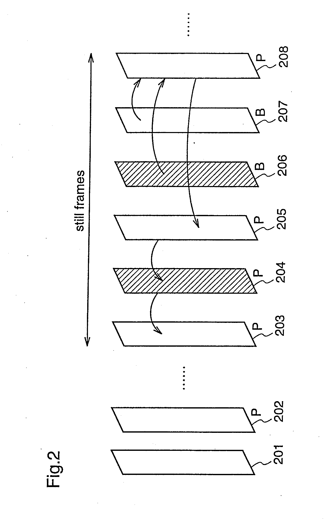
[0066]An image coding apparatus 100 according to the first embodiment performs one-pass coding in which a target image signal is coded only once, and the apparatus 100 judges whether a frame to be coded is a still frame or not, and subjects a frame next to (one frame after) a frame that starts to come into a standstill (a frame immediately previous to the frame judged as a still frame), to a coding process (still frame coding) which provides a higher image quality than those of other frames.

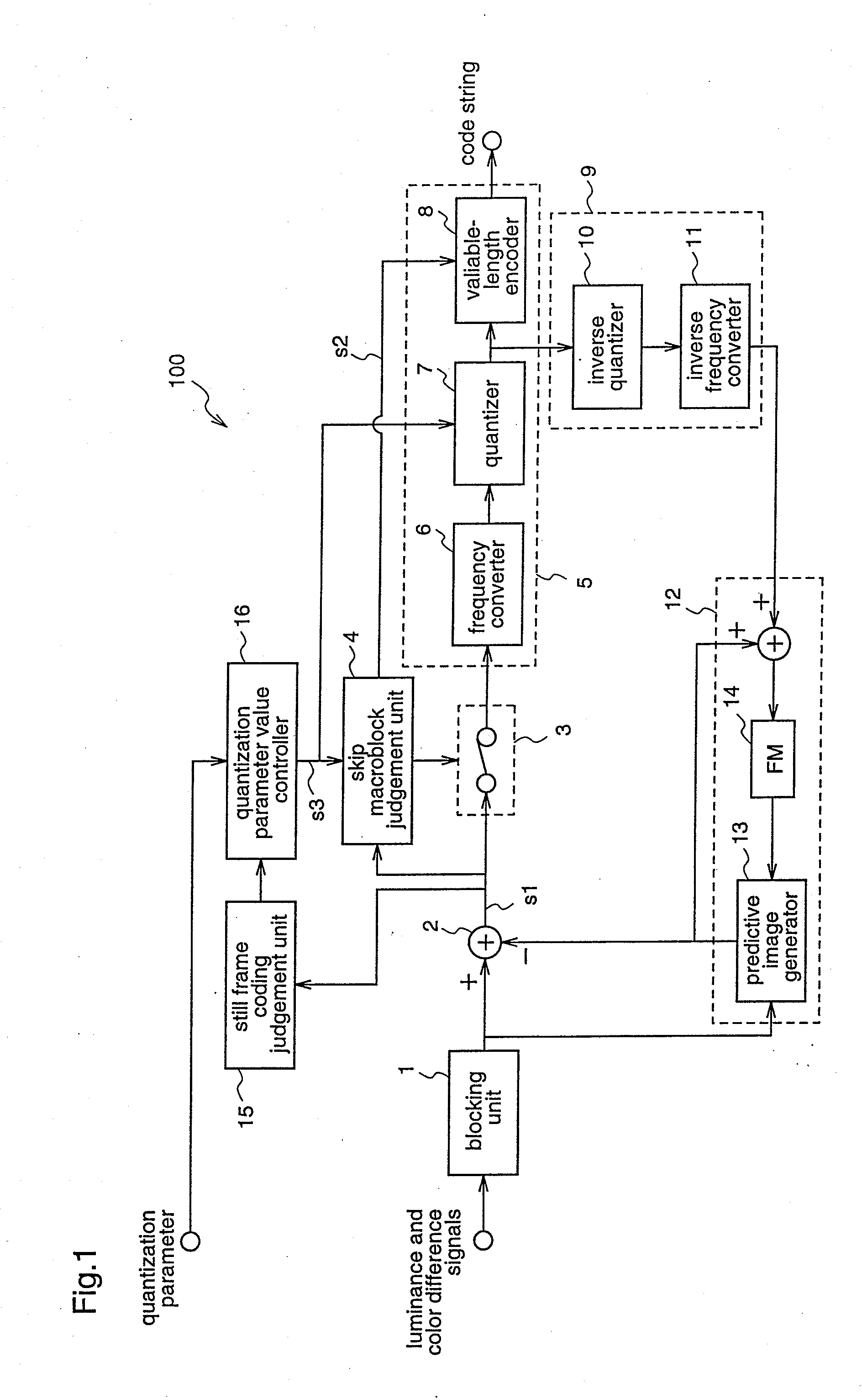
[0067]FIG. 1 is a block diagram illustrating the construction of the image coding apparatus 100 according to the first embodiment. Since, in FIG. 1, the same reference numerals as those shown in FIG. 16 denote the same or corresponding components, repeated description is not necessary.

[0068]In FIG. 1, reference numeral 15 denotes a still frame coding j...

embodiment 2

[0116]Hereinafter, an image coding apparatus and an image coding method according to a second embodiment of the present invention will be described.

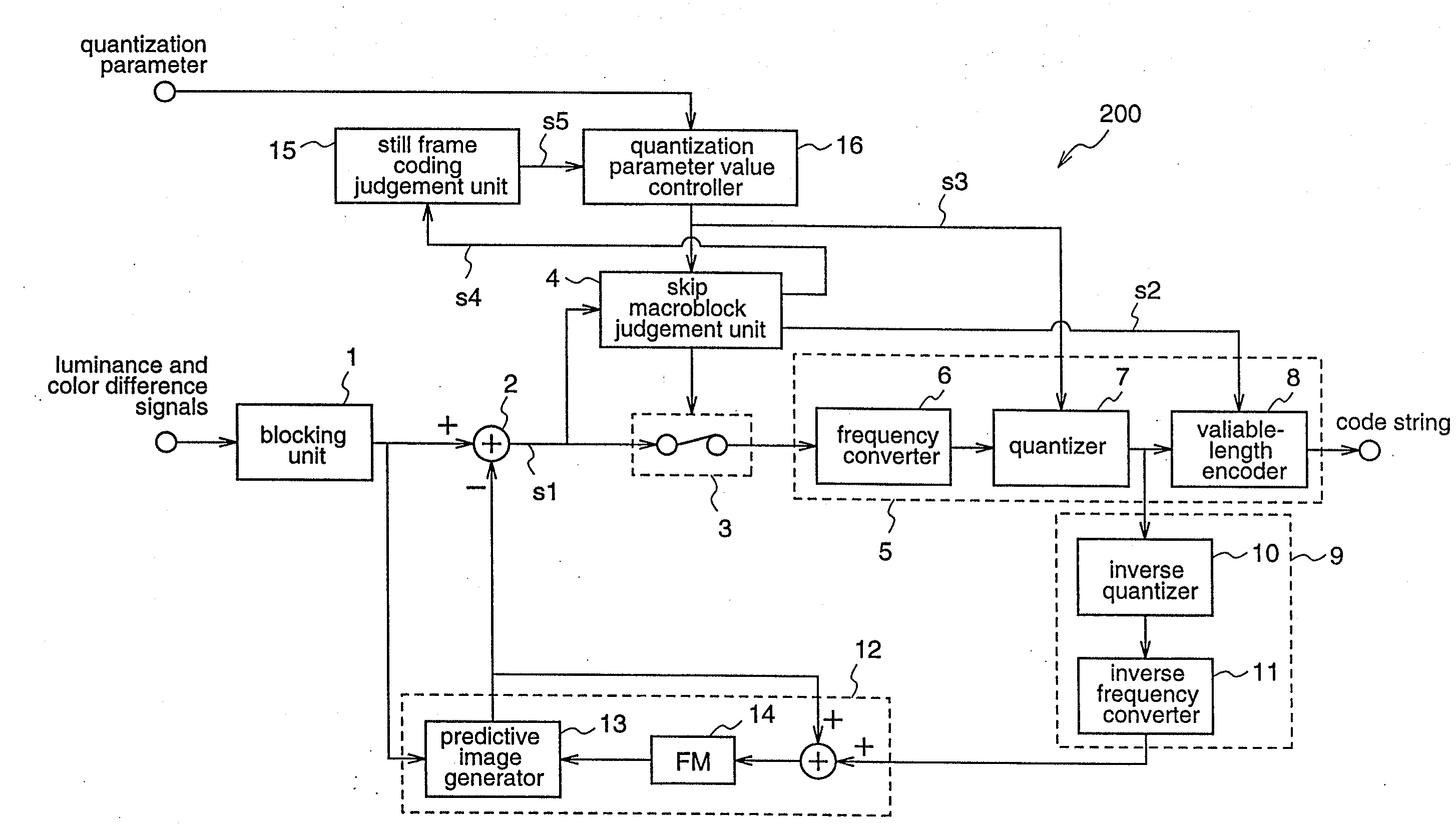
[0117]An image coding apparatus 200 according to the second embodiment has a construction as shown in FIG. 9. The image coding apparatus 200 determines a still frame in an image to be coded, and subjects a frame positioned two frames after a frame which starts to come into a standstill, to a coding process that realizes higher image quality (still frame coding) as compared coding for other frames.

[0118]The image coding apparatus 200 according to this second embodiment is different from the image coding apparatus 100 according to the first embodiment performing one-pass coding reside, in processing performed by the still frame coding judgement unit 15 for judging whether still frame coding should be carried out or not, and in processing performed by the quantization parameter value controller 16. Hereinafter, these differences will be des...

embodiment 3

[0149]Hereinafter, an image coding apparatus and an image coding method according to a third embodiment of the present invention will be described.

[0150]An image coding apparatus 300 according to this third embodiment has a construction as shown in FIG. 13. The image coding apparatus 300 determines a still frame in an image to be coded, and subjects a frame two frames after a frame that starts to come into a standstill, to a coding process which provides higher image quality (still frame coding) as compared with coding for other frames.

[0151]The image coding apparatus 300 according to the third embodiment is different from the image coding apparatus 200 according to the second embodiment in processing performed by the still frame coding judgement unit 15 that judges whether still frame coding should be performed or not, and in processing performed by the skip macro block judgement unit 4. Therefore, only these differences will be described hereinafter.

[0152]Initially, the operation ...


PUM


Abstract

An image coding apparatus includes a still frame coding judgement unit for judging whether a target frame to be coded is a still frame or not from a difference value between the target frame and an immediately previous reference frame, and a quantization parameter control unit for performing control of a quantization parameter value to be used for coding, on an initial one frame at which an image starts to come into a standstill, wherein the initial frame is subjected to coding with less coding error as compared with coding for other frames.

Description

[0001]This application is a divisional application of application Ser. No. 10 / 341,350, filed Jan. 14, 2003.FIELD OF THE INVENTION[0002]The present invention relates to an image coding apparatus, an image coding method, and an image coding program and, more particularly, to those for specifying a still frame among target frames to be coded, and coding the still frame with high image quality.BACKGROUND OF THE INVENTION[0003]In order to store or transmit a digital image with high efficiency, it is necessary to compressively coding the digital image. As a method for compressively coding a digital image, there is a waveform coding method such as subband coding, wavelet coding, or fractal coding, besides discrete cosine transform (DCT). In coding an image, the image is compressed by removing redundant data within a frame when the image has similar portions within the frame, or by removing redundant data between frames, such as still portions, from continuous display frames, and then the c...

Claims


Application Information

Patent Timeline
Patent Type & Authority Applications(United States)
IPC IPC(8): G06K9/36H04N7/26H04N7/36H04N7/50
CPCH04N19/197H04N19/105H04N19/503H04N19/159H04N19/176H04N19/132H04N19/196H04N19/149H04N19/61H04N19/107H04N19/172
Inventor UCHIBAYASHI, KYOKOHAGAI, MAKOTO
Owner SOVEREIGN PEAK VENTURES LLC
Why Eureka
Try Eureka