
Spherical plain bearing with spread sealing means

a technology of sealing members and bearings, which is applied in the direction of crankshafts, couplings, mechanical equipment, etc., can solve the problems of configurations that are easy to be easily removed, and sealing members that are often undesirable, so as to enhance sealing communication, effective sealing and wiping of bearing surfaces, and enhanced lubrication

Inactive Publication Date: 2009-01-08
ROLLER BEARING OF AMERICA
View PDF19 Cites 11 Cited by
  • Summary
  • Abstract
  • Description
  • Claims
  • Application Information

AI Technical Summary

Benefits of technology

The present invention is a spherical plain bearing with dual sealing capability. The bearing has an outer race and an inner race with an opening defined by the outer ring. The inner ring has a spherical concave surface engaging with the outer ring's spherical convex surface. The bearing has two seals, each with two lips, that provide a v-shaped cross-sectional geometry and allow for effective sealing and wiping even after extended use. The seals also enhance lubrication, minimize contamination, and provide a self-adjusting characteristic. The dual sealing configuration allows for flushing degraded or contaminated lubricant out of the load zone by forcing fresh lubricant into the sealing member via a lubricant aperture. The heat treatment of the inner and outer rings increases the durability of the bearing.

Problems solved by technology

These configurations have a natural tendency to be easily removed after wear has occurred (either inadvertently or intentionally) or to be difficult to position in place initially.
Furthermore, these sealing members are often undesirably located on the edges of the ring members of the bearings and adjacent to the contact surfaces of the load zone.
When located on the edges of the ring members and adjacent to the contact surfaces of the load zone, the sealing members are easily damaged and / or dislodged, which makes it harder to maintain the seal to retain the lubricant in the load zone.
Furthermore, the wiping function of the seal (ability to spread the lubricant on the bearing surface proximate the area at which the seal contacts the bearing surface) may be compromised.

Method used


Image

  • Spherical plain bearing with spread sealing means
  • Spherical plain bearing with spread sealing means
  • Spherical plain bearing with spread sealing means

Examples


Embodiment Construction

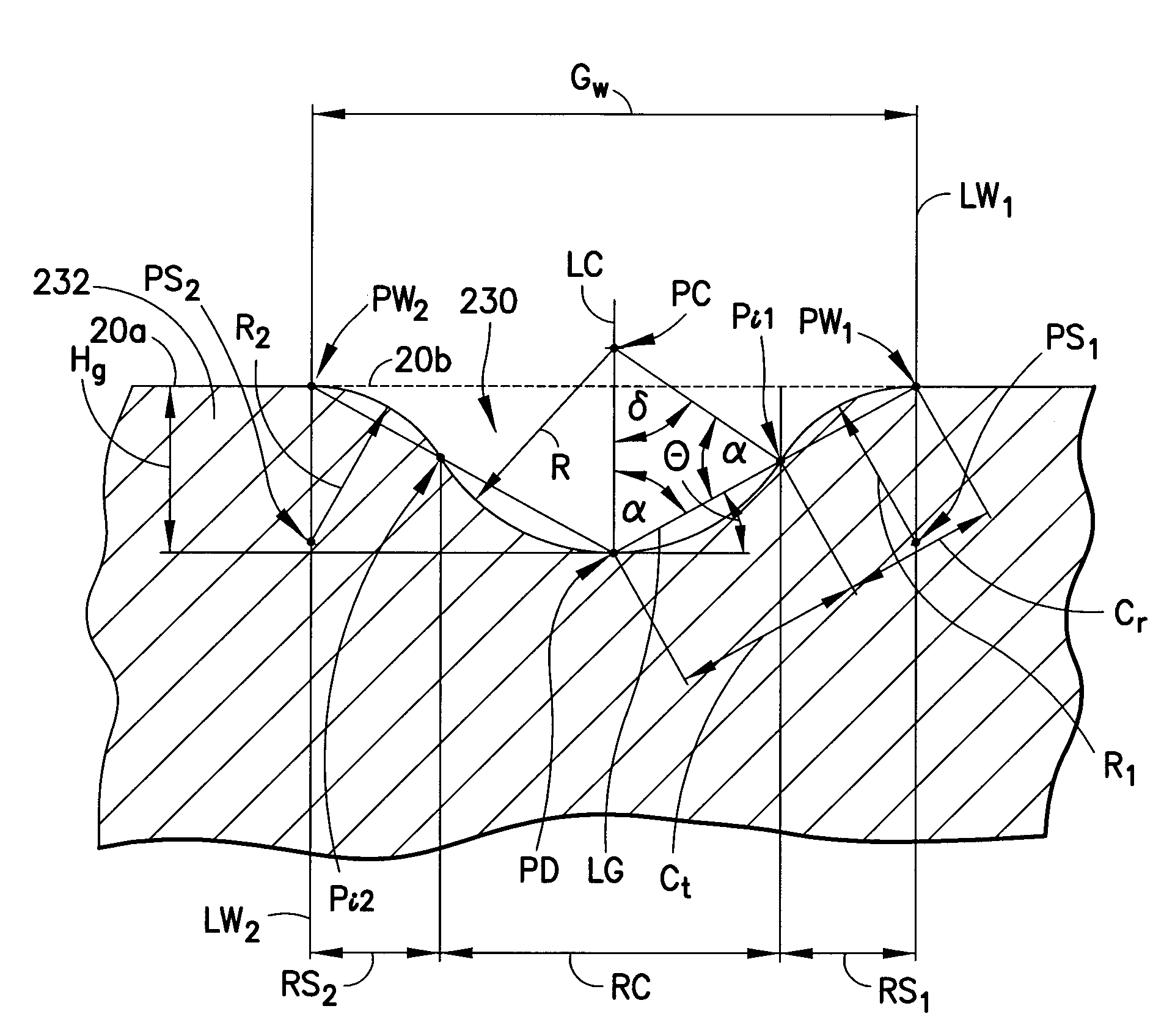
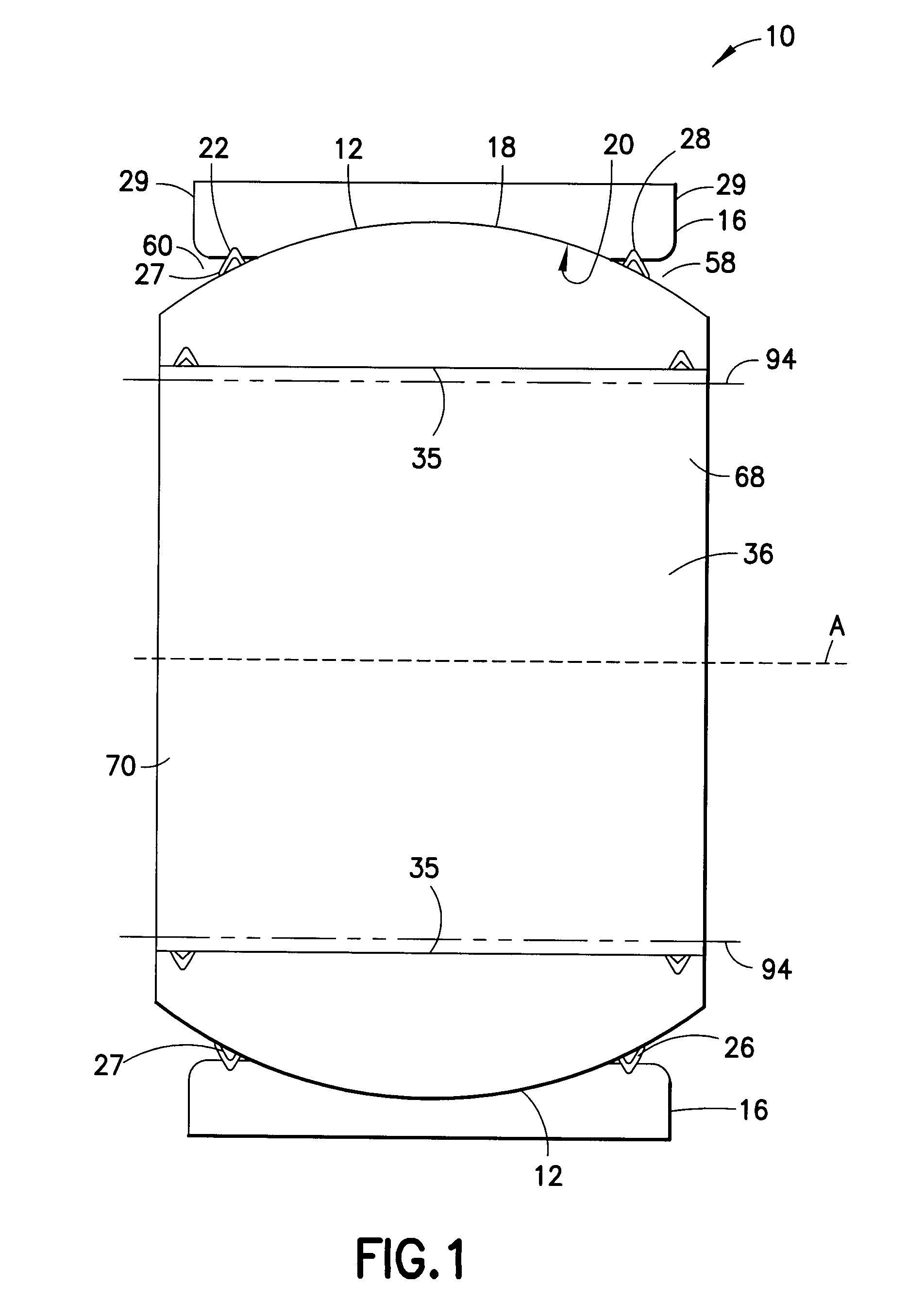
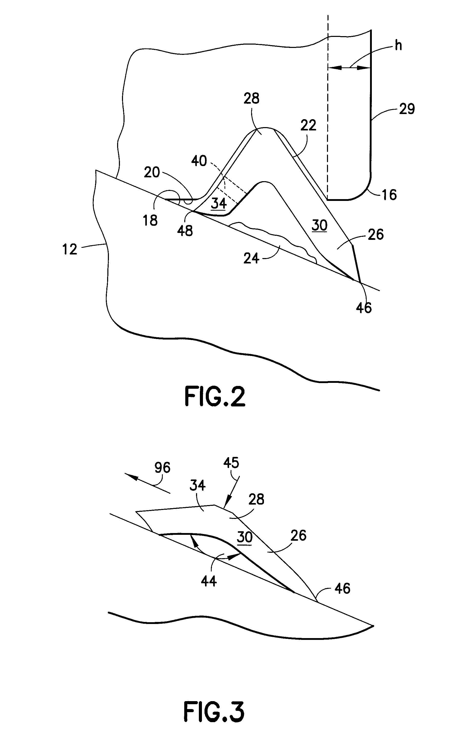
[0027]As shown in FIG. 1, a spherical plain bearing is designated generally by the reference number 10 and is hereinafter referred to as “bearing 10.” Bearing 10 includes an inner ring 12 and an outer ring 16. The inner ring 12 has an annular configuration that defines a central axis and has a spherical convex bearing surface 18. The inner ring 12 also has an interior peripheral surface 35 that defines a bore 36 that extends through the inner ring. The bore 36 includes a first opening 68 at one end thereof and a second opening 70 at an opposite end thereof. The outer ring 16 has an annular configuration that also defines a central axis. The outer ring 16 has a spherical concave bearing surface 20 and is open at a first axial end 58 and a second axial end 60. The outer ring 16 and the inner ring 12 are through hardened. When the bearing 10 is assembled, the spherical convex bearing surface 18 and the spherical concave bearing surface 20 reside in interfacial engagement with one anoth...


PUM


Abstract

A spherical plain bearing having dual sealing capability includes an outer race bearing member having an outer ring and an inner race bearing member having an inner ring, the inner ring being located within an opening defined by the outer ring. The opening is defined in part by two generally opposed peripheral edges with a spherical concave bearing surface extending therebetween. The inner ring defines a bore extending therethrough and a spherical convex bearing surface engagable with the concave bearing surface defined by the outer ring. A first ring seal is positioned in a first seal groove defined by the outer ring and is inboard of a first face surface defined by the outer ring. The outer and inner rings, or at least portions thereof, are heat treated using one of carburizing, nitriding, or nitrocarburizing.

Description

CROSS REFERENCE TO RELATED APPLICATION[0001]This application is a continuation-in-part application of U.S. Ser. No. 11 / 880,138, filed Jul. 19, 2007, which claims the benefit of U.S. provisional application No. 60 / 832,054 filed Jul. 19, 2006, which is incorporated herein by reference in its entirety.TECHNICAL FIELD[0002]This invention relates to spherical plain bearings and, more particularly, to a spherical plain bearing having spread sealing members.BACKGROUND OF THE INVENTION[0003]Spherical plain bearings generally include inner and outer ring members wherein the outer ring member has a spherical concave interior surface that defines a cavity therein and wherein the inner ring member is disposed in the cavity and has a spherical convex surface that is complementary to, and is dimensioned to match, the interior concave surface of the outer ring member. In the assembled bearings, the concave and convex surfaces slide over each other to define the bearing surfaces or “load zone.”[000...

Claims


Application Information

Patent Timeline
Patent Type & Authority Applications(United States)
IPC IPC(8): F16C33/10F16C11/06
CPCF16C33/1065F16C33/74Y10T403/257F16C33/103F16C23/045F16C2240/70F16C2240/42
Inventor GAUMER, BRIANLUGOSI, ROBERTVOISINE, JAMES
Owner ROLLER BEARING OF AMERICA
Learn More