
Partial cuff

a technology of cuff and sling, which is applied in the field of surgically implantable flow restrictors, can solve the problems of inability to precisely adjust the sling tension for each patient, lower than expected efficacy, and inability to punch the bladder and/or blood vessels, etc., and achieves the effect of minimally invasive surgical procedures and simple surgery

Active Publication Date: 2009-01-08
TIHON CLAUDE
View PDF14 Cites 84 Cited by
  • Summary
  • Abstract
  • Description
  • Claims
  • Application Information

AI Technical Summary

Benefits of technology

[0012]The invention provides a simple, minimally invasive surgical procedure. It allows adjustments after surgery and after tissues have healed by providing positive pressure to achieve the right amount coaptation needed by the patients condition. The invention allows natural and volitional voiding for incontinent patients.

Problems solved by technology

All three approaches involve the use of long rods passing blindly from one anatomical site to the other, and often resulting in puncturing of the bladder and / or blood vessels.
Though the transobturator approach avoids the retropubic space and does not lead to puncturing of the bladder, it suffers as the other two in that it involves anatomical structures outside of the urinary tract system and thus, typically, not familiar to urological surgeons.
In addition, a precise adjustment of the sling tension for each patient is not possible.
This ill adjustment results in lower than expected level of efficacy and complications including urethral erosions.
Furthermore, as the sling is being anchored in anatomical structures other than the urethra, it presents complications, such as injuries to bladder, blood vessels, nerves and muscles and is contraindicated for women patients who intend to have child births in the future.
The AUS is a complex system and the associated surgical procedure is major, complex and long.
All these tubes can suffer from defects and lose their intended function in controlling flow of material and fluids within them.

Method used


Image

  • Partial cuff
  • Partial cuff
  • Partial cuff

Examples


Embodiment Construction

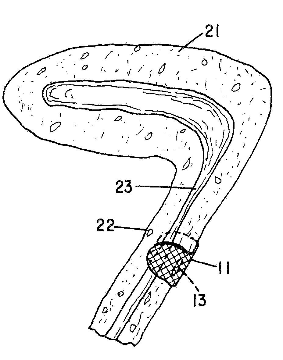
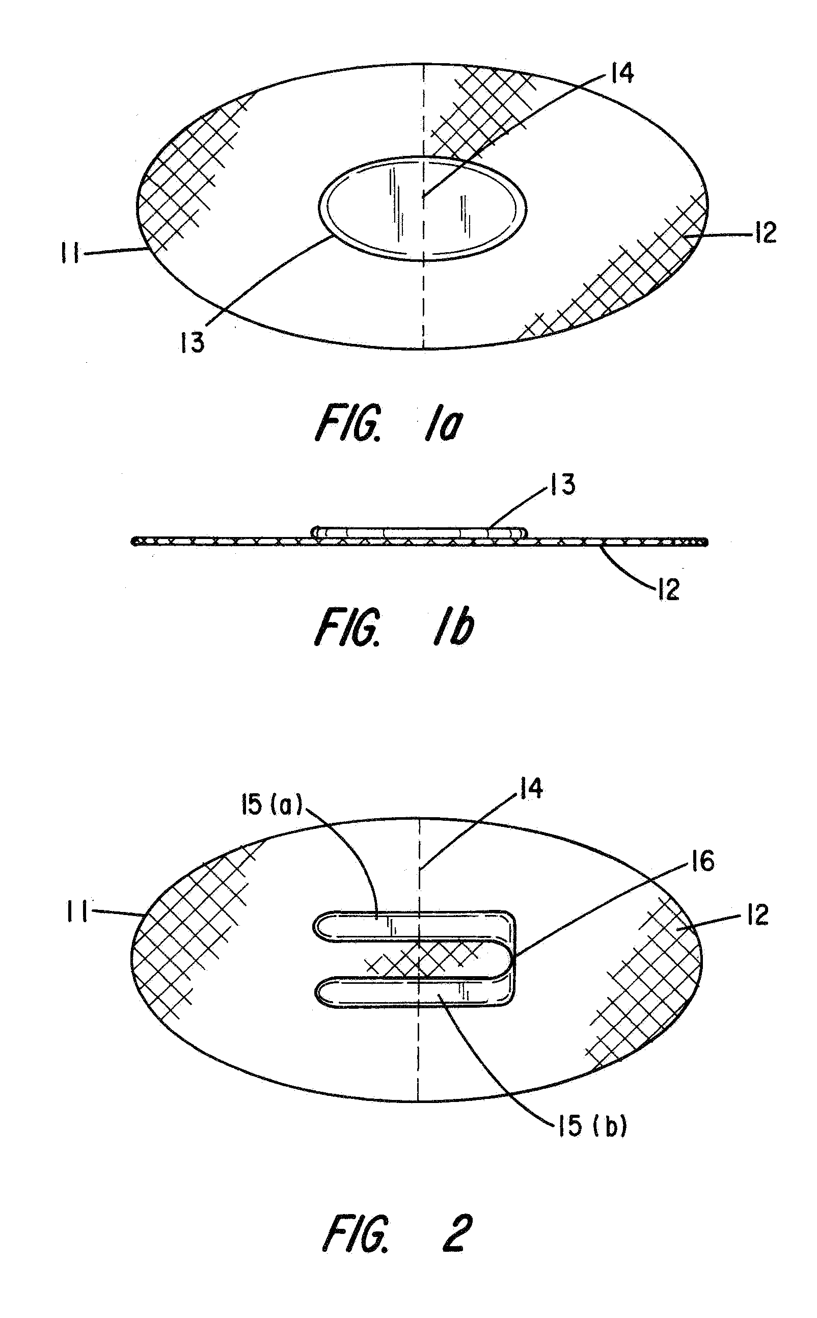
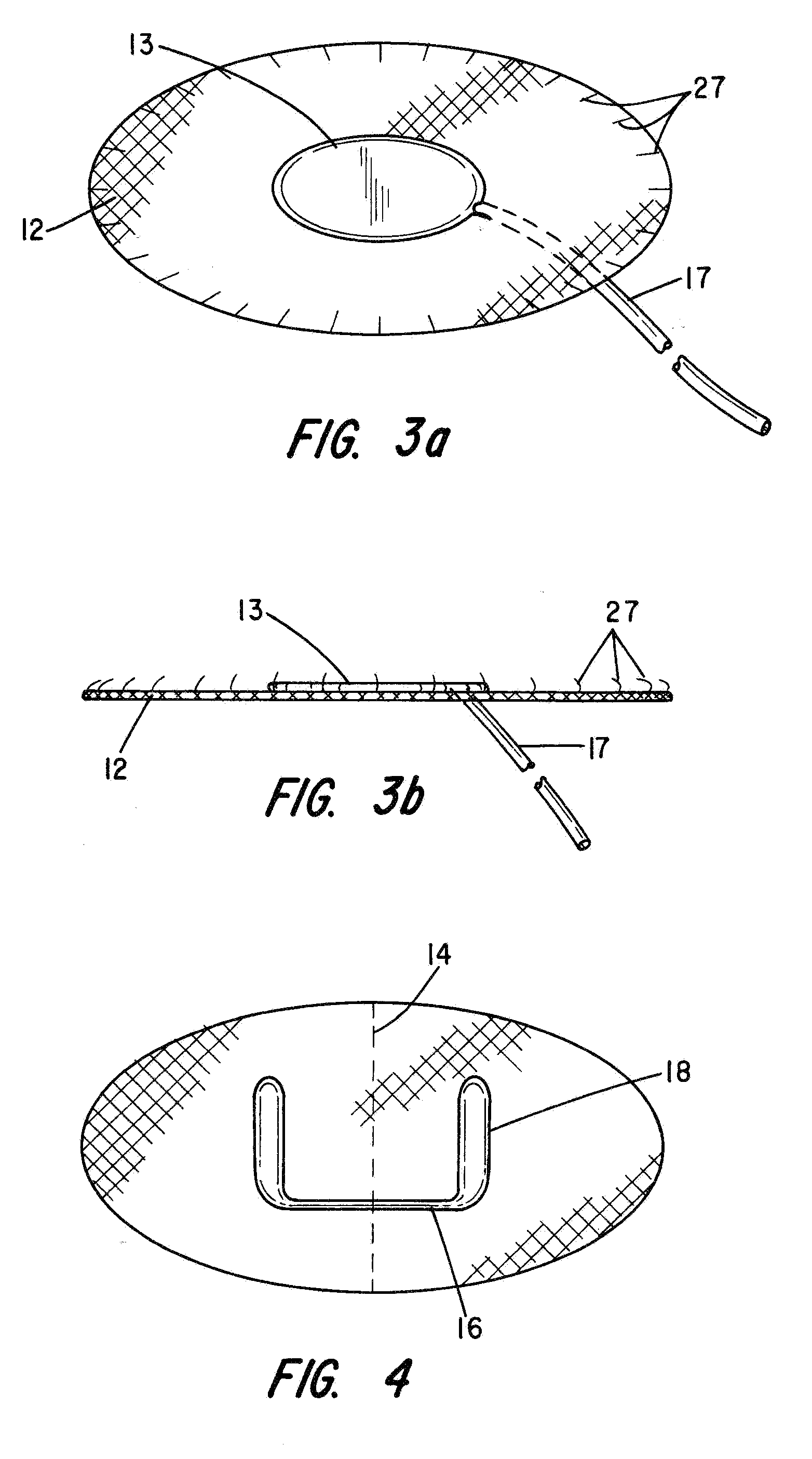
[0033]Referring to FIGS. 1a and 1b of the drawings, the partial cuff 11, comprising a first embodiment, is seen to include a flexible base member 12 that is preferably a synthetic mesh-like fabric formed from polypropylene strands like those used in surgical repair of hernias and urethral slings. That type of mesh is bio-compatible and accommodates tissue ingrowth through the interstices of the mesh material.

[0034]Without limitation, the mesh base member 12 may be generally oval or elongated in shape having a major axis measuring about 3 cms and a minor axis of about 1½ cms when the device is to be used in addressing female urinary incontinence.

[0035]In accordance with a first aspect of the invention, there is affixed to the flexible, mesh base member 12 an expandable component 13 having a predetermined shape configuration and generally centrally disposed on one major surface of the flexible base member 12. The expandable component 13 may comprise an elastomeric balloon capable of b...


PUM


Abstract

To increase the resistance to liquid and substance flow through a lumen of a tubular organ, a cuff comprising a flexible, mesh base member is appended to an exterior wall of the tubular organ such that it only partially surrounds the tubular organ. Ultimately, tissue ingrowth through the mesh base member integrates the cuff into the wall of the tubular organ. When the cuff is applied to the urethra of an incontinent patient, the increased resistance to flow renders the patient continent while still allowing normal voiding. The base member may also support an optional expandable component, e.g., a balloon-like element that can be selectively inflated and / or deflated to restrict the lumen of the tubular organ by a desired degree.

Description

CROSS-REFERENCE TO RELATED APPLICATION[0001]This application claims priority to Provisional application Ser. No. 60 / 958,420, filed Jul. 6, 2007, and Provisional application Ser. No. 61 / 011,750, filed Jan. 22, 2008, the contents of which are hereby incorporated by reference.BACKGROUND OF THE INVENTION[0002]1. Field of the Invention[0003]The invention relates generally to surgically implantable flow restrictors, and more particularly to a cuff that is attachable directly to a tubular organ for increasing the flow resistance of liquids and substances through the tubular organ.[0004]2. Discussion of the Prior Art[0005]Biological tubular organs in our body are conduits for fluids, food and wastes. For example, the urethra is the conduit for urine between the bladder and the urethral meatus and it also functions to inhibit involuntary leakage. In stress urinary incontinence, urine leaks involuntarily when the person coughs or laughs.[0006]Stress urinary incontinence occurs most commonly i...

Claims


Application Information

Patent Timeline
Patent Type & Authority Applications(United States)
IPC IPC(8): A61F2/02
CPCA61B17/12A61B17/282A61F2/0036A61F2/004A61F2210/0066A61F2/06A61F2002/044A61F2002/30077A61F2/0063
Inventor TIHON, CLAUDE
Owner TIHON CLAUDE
Learn More