
Application level integration in support of a distributed network management and service provisioning solution

Inactive Publication Date: 2009-01-08
ALCATEL LUCENT SAS
View PDF8 Cites 9 Cited by
  • Summary
  • Abstract
  • Description
  • Claims
  • Application Information

AI Technical Summary

Benefits of technology

[0033]In accordance with a further aspect of the invention, a method of exchanging information between software applications in a network management and service provisioning environment is provided. The method includes a sequence of steps. At least one iconical representation of a data network entity displayed in conjunction with a first software application is selected. At least one object identification (objectID) associated with the selection is extracted. The at least one objectID is conveyed to a second software application. And, using the conveyed objectID, at least one parameter specifier associated with the second application is populated. The exchange of objectID information facilitates an integrated network management and service provisioning environment.
[0034]The information exchange may further extract at least one parameter value associated with the selection. The at least one parameter value is conveyed to the second application. And, the at least one conveyed parameter value is used to populate at least one parameter specifier associated with the second application. The exchange of the at least one parameter value further facilitates the integrated network management and service provisioning environment.
[0035]The advantages are derived from a data network and service management solution integration provisioning the exchange of information between enabling applications. A combination of application code may be executed concurrently and the man-machine interface is integrated to provide a seamless object selection, property cut, property copy, property paste, etc. functionality. The solution integration further provides distributed application launching, secure user authentication and authorization, secure interaction via the man-machine interface including the enforcement of scope of command and span of control.

Problems solved by technology

Typically the legacy computers running legacy software application code are no longer sold, no longer maintained and / or supported actively.
All these factors compound resulting in increased costs for supporting legacy software application code curtailing further development thereof.
Computer hardware cost is another factor.
This arrangement may not always be viable.
In making reference to application code “not being aware” of other application code, it is understood that the combination of application code does not have facilities for interaction therebetween including a lack of facilities for information exchange.
The repeated information entry actions are time consuming and error prone leading to an inefficient provisioning of the solution.
Such information exchange facilities available are limited to text level “cut / copy / paste” functionality as a remedy to repeated multiple entry tasks.
Although somewhat helpful, the available information for cut / copy / paste is limited to displayed information which leads to an information exchange having a very shallow scope.
Further, these facilities are not adequate, as it is typically the case, when the multiple entries, although pertaining to the same information, do not have the same data entry format (e.g. date / time formats, units of measure, etc.)
In some cases the legacy software application code 314 was designed pushing the legacy computers 310 to their performance limits; therefore extending the legacy software application code 314 to include the new features would severely affect the performance thereof.
Typically legacy code is regarded as stable leading to a reluctance to fix that which is not broken.
Further, using this approach would not provide a long term solution since new features are demanded on a continuing basis by market drivers.
Once again using this approach does not provide a long term solution as computers are under an ongoing development and as new computers become available the recoding would have to be undertaken again.

Method used


Image

  • Application level integration in support of a distributed network management and service provisioning solution
  • Application level integration in support of a distributed network management and service provisioning solution
  • Application level integration in support of a distributed network management and service provisioning solution

Examples


Embodiment Construction

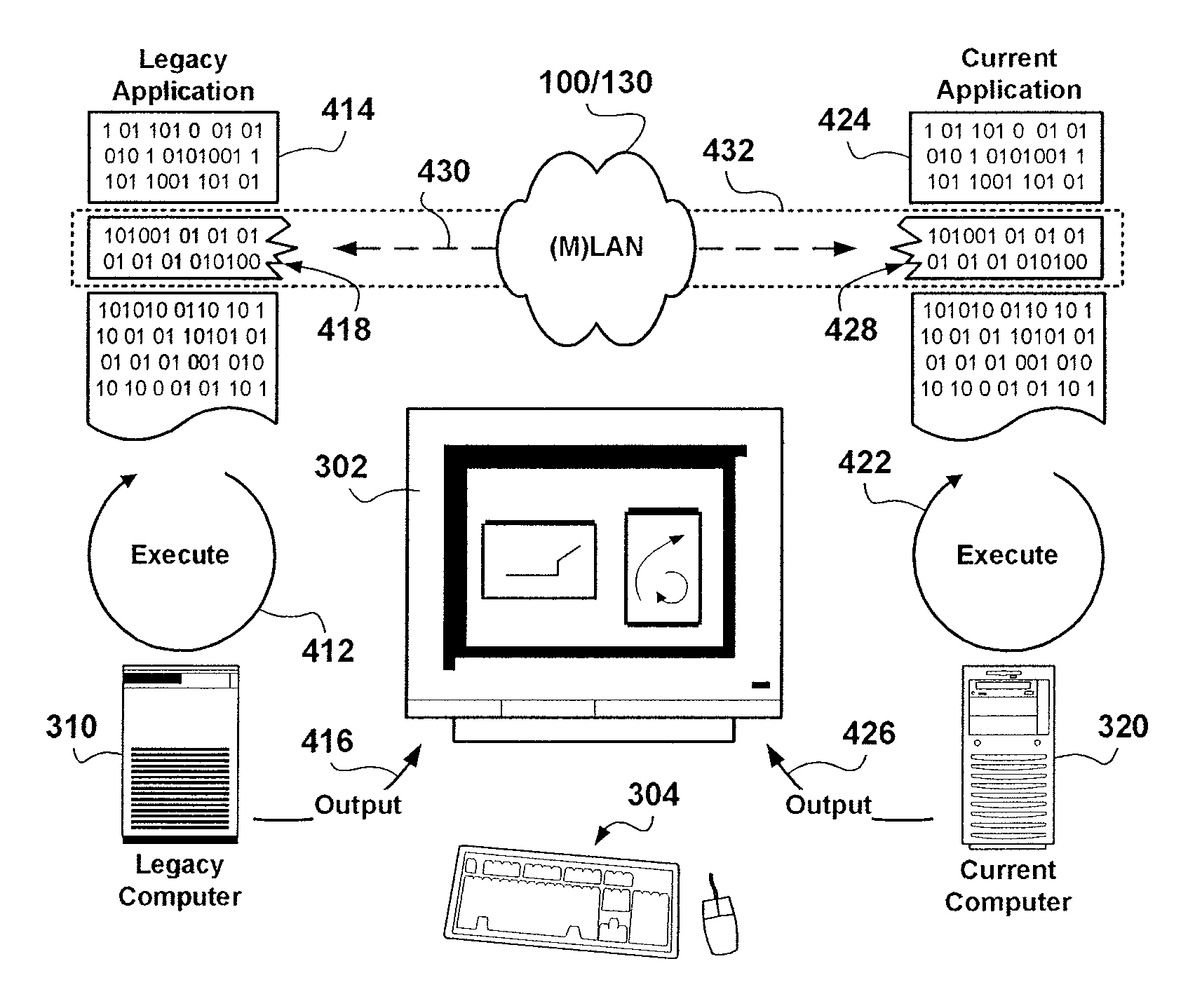
[0045]FIG. 4 is a schematic diagram showing, in accordance with a preferred embodiment of the invention, a detail of a network management and data service provisioning environment facilitating the presentation of a current data network state and providing an interaction therewith.

[0046]In accordance with a preferred embodiment, legacy software application code 414 is augmented with a code portion 418, as well current software application code 424 is augmented with a code portion 428. The application code change via the augmentation of at least one code portion (418 / 428) is performed only once per application to include provisions for information exchange 430.

[0047]The one time augmentation of the existing (current and legacy) application code with code portions 418 / 428 removes the necessity of future recoding thereof. In accordance with the invention, a process of development of new application code includes requirements for the support of an interworking layer 432 to enable the inf...


PUM


Abstract

An integrated data network management and data service provisioning environment is provided. The integrated environment includes legacy software application code and current software application code each augmented with code portions enabling exchange of information therebetween via an interworking layer. A facility for participation in and interacting with the integrated environment is also provided. A man-machine interface is integrated across different applications which themselves may be executed on different computers to provide a seamless exchange of information. The advantages are derived from enhanced usage efficiencies in providing data network management and service provisioning solutions. The interworking layer also provides for security enforcement across applications participating in the integrated environment.

Description

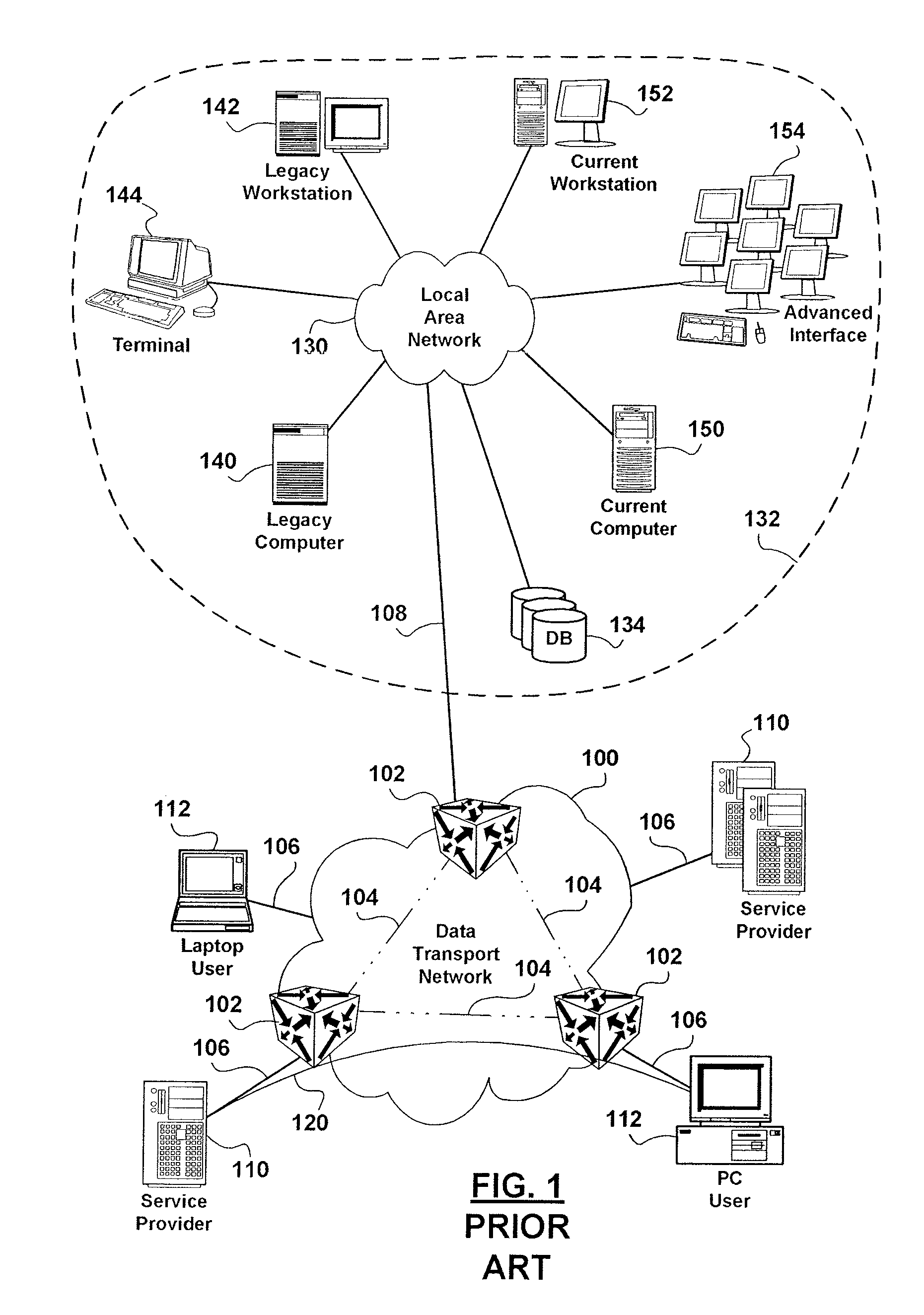
FIELD OF THE INVENTION[0001]The invention relates to data network management and data service provisioning environments, and in particular to methods of using network management and service provisioning applications in combination to provide network management and service provisioning solutions.BACKGROUND OF THE INVENTION[0002]In the field of data network management and service provisioning, software applications running on and hardware associated with computing platforms such as workstations, computers, terminals, etc. are used in combination to provide network management and service provisioning solutions.[0003]FIG. 1 is a schematic diagram showing data network elements participating in a data transport network and data network elements used in an associated data network management and data service provisioning environment.[0004]A data transport network 100 includes data network nodes such as, but not limited to, data switching nodes 102, and interconnecting data transport links 1...

Claims


Application Information

Patent Timeline
IPC IPC(8): H04L9/00G06F9/44G06F9/46H04L12/24
CPCG06F9/4443H04L41/22H04L43/0817H04L41/5096H04L41/5012G06F9/451
Inventor BAWA, SATVINDER SINGH
Owner ALCATEL LUCENT SAS
Learn More