
Roll Formed Flexible Die Plate For Rotary Cutting Tool

a flexible die plate and rotary cutting technology, applied in cutting tools, metal working devices, manufacturing tools, etc., can solve the problems of increasing the cost of die cylinders, the cost of magnets, and the cost of machining, and achieve the effect of low cost and high quality

Inactive Publication Date: 2009-01-15
EAGLE ROTARY SYST
View PDF1 Cites 21 Cited by
  • Summary
  • Abstract
  • Description
  • Claims
  • Application Information

AI Technical Summary

Benefits of technology

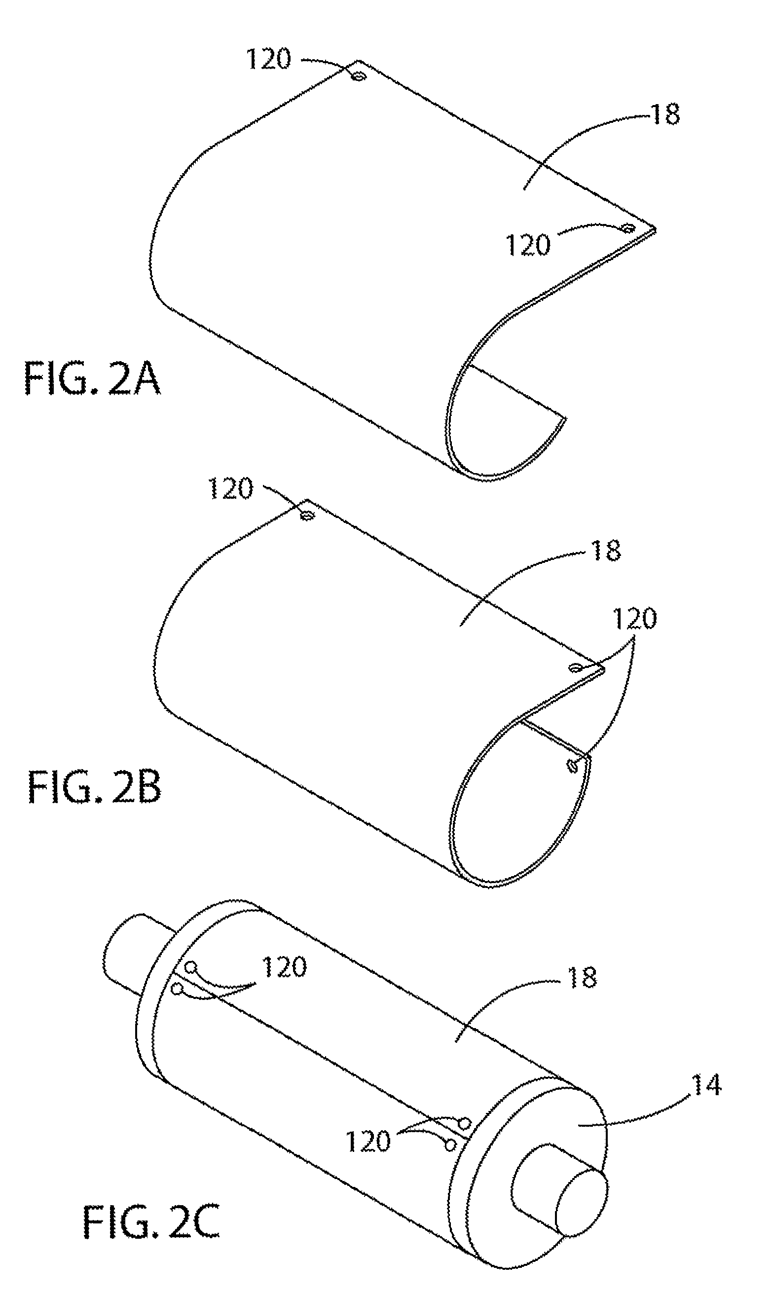
[0007]In accordance with a first aspect, a method of making a rotary cutting tool for cutting a web of material comprises the steps of roll forming a first flexible die plate into a cylindrical shape, mounting the cylindrically shaped die plate onto a cylindrically shaped fixture, and machining cutting elements onto the roll formed die plate. The roll formed die plate may then be removed from the fixture and attached to a cylinder. The first die plate can cooperate with a second die plate attached to a second cylinder to cut the thin web of material. Optionally the die plate may be roll formed a second time with a radius generally equal to a...

Problems solved by technology

However, such a design greatly increases the costs of the die cylinders for several reasons, including the cost of the magnets, the cost of machining holes into the cylinders to receive the magnets, and the difficulty in assembly.
There are numerous limitations in the chemical etching process, both in terms of limitations in the properties of the die pates made by the process and difficulties in the process for assembling the die plates to the cylinders.
For example, tool steels (steels with large amounts of non-ferrite alloys) are more difficult to chemically etch.
Chemical etching works better with carbon steels, but carbon steels are relatively brittle and not ideal for forming, bending and other operations.
Also, some geometries such as undercuts are difficult to make.
With regards to the process, use of magnets requires extensive machining of cylinders, thereby making such cylinders quite expensive.
Further, both magnets and welding die plates to the cylinder require extensive changeover time when switching die plates, undesirably increasing downtime for printing.
Known chemically etched flexible die plates are awkward to assemble with the cylinder.

Method used


Image

  • Roll Formed Flexible Die Plate For Rotary Cutting Tool
  • Roll Formed Flexible Die Plate For Rotary Cutting Tool
  • Roll Formed Flexible Die Plate For Rotary Cutting Tool

Examples


Embodiment Construction

[0018]It will be apparent to those skilled in the art, that is, to those who have knowledge or experience in this area of technology, that many uses and design variations are possible for the rotary cutting tool disclosed here. The following detailed discussion of various alternative and preferred features and embodiments will illustrate the general principles of the invention with reference to a rotary cutting tool suitable for use in industrial applications where flat paperboard-like materials are to be cut. Other embodiments suitable for other applications will be apparent to those skilled in the art given the benefit of this disclosure.

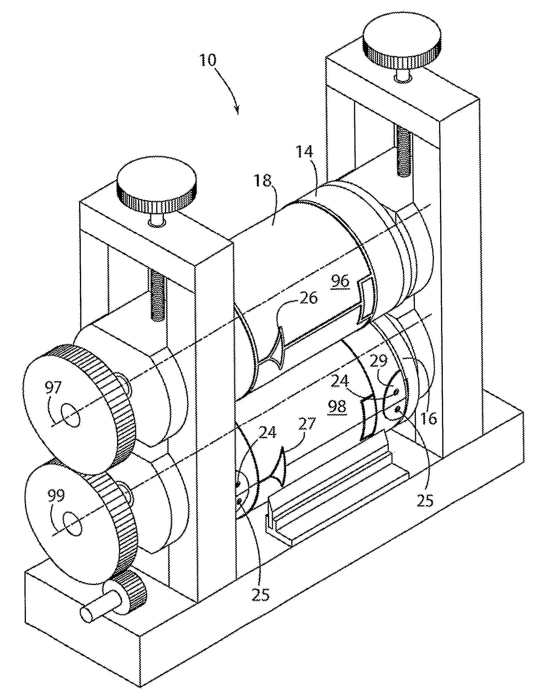
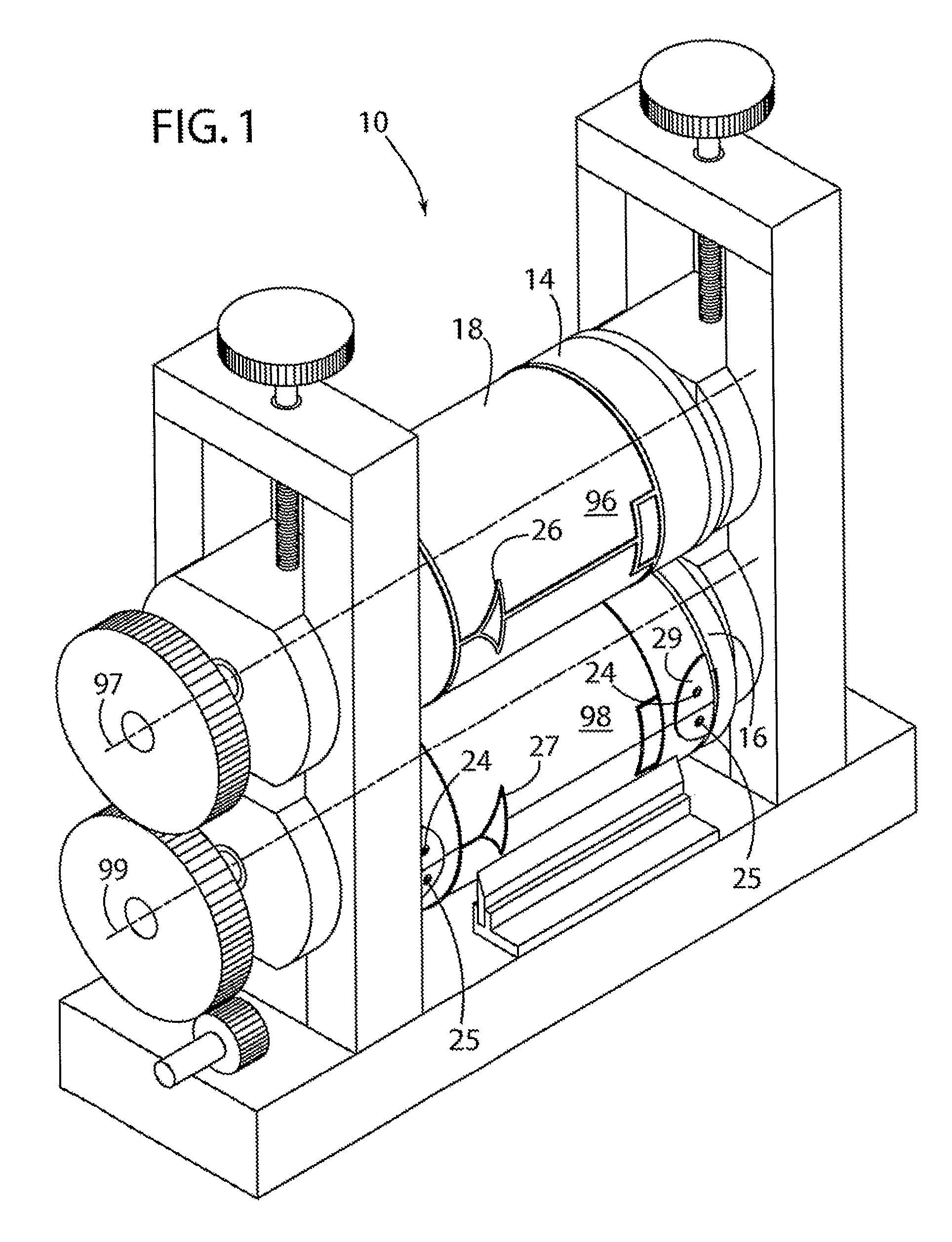
[0019]Referring now to the drawings, FIG. 1 shows a rotary cutting tool 10 in accordance with a preferred embodiment having an upper die cutting assembly 96 and a lower die cutting assembly 98. The upper die cutting assembly has a cylinder 14 and die plate 18 wrapped around the cylinder, and the lower die cutting assembly 98 has a cylinder 16 and ...


PUM

PropertyMeasurementUnit
Sizeaaaaaaaaaa
Flexibilityaaaaaaaaaa
Shapeaaaaaaaaaa

Abstract

A method of making a rotary cutting tool for cutting a web of material comprises the steps of roll forming a first flexible die plate into a cylindrical shape, mounting the cylindrically shaped die plate onto a cylindrically shaped fixture, and machining cutting elements onto the roll formed die plate. The roll formed die plate may then be removed from the fixture and attached to a cylinder. The first die plate can cooperate with a second die plate attached to a second cylinder to cut the thin web of material.

Description

RELATED APPLICATION[0001]This application is a 35 U.S.C. §371 national phase application of PCT / US2007 / 060262, filed Jan. 9, 2007, which claims priority benefit of U.S. provisional patent application No. 60 / 757,799 filed on Jan. 10, 2006.FIELD OF THE INVENTION[0002]This invention relates to improvements in rotary cutting tools and more particularly to improvements in flexible die plates for rotary cutting tools.BACKGROUND OF THE INVENTION[0003]Rotary cutting tools are useful for manufacture of carton blanks and other workpieces from sheets or webs of material. In particular, rotary die cutting tools are used in high speed cutting of a moving sheet or web of paper, paperboard, plastics or composite materials. As one example, rotary die cutting machines are used for the high speed mass production of paperboard carton blanks that are subsequently folded into the shape of cartons or boxes such as cereal and cracker boxes, etc. Rotary cutting tools include solid rotary dies, where the cu...

Claims


Application Information

Patent Timeline
IPC IPC(8): B21K5/20
CPCB23P15/406B26D7/2614B26F1/44B26F1/384B26D2007/2607
Inventor PFAFF, JR., ALAN R.
Owner EAGLE ROTARY SYST
Learn More