
Heat dissipation module

Inactive Publication Date: 2009-01-15
ASUSTEK COMPUTER INC
View PDF14 Cites 15 Cited by
  • Summary
  • Abstract
  • Description
  • Claims
  • Application Information

AI Technical Summary

Benefits of technology

[0010]In the heat dissipation module of the invention, the first radiating fin assembly is assembled at the inside wall of the frame and is located on the flow channel between the frame and the blade set. The airflow generated by the fan can remove the heat energy which is conducted to the first radiating fin assembly from a heat source while the airflow flows through the flow channel. Since the first radiating fin assembly is assembled at the inside wall of the frame of the fan, the heat dissipation module has a less production volume and is suitable to be provided in a computer housing which has limited inner space to dissipate the heat for the heat source in the housing.

Problems solved by technology

However, since a notebook computer on the market is developed to be light and slim, and the inner space of the notebook computer is limited, the mode of additionally disposing a radiating fin assembly outside the air outlet of the fan is difficult to be applied to the notebook computer having limited inner space.

Method used


Image

  • Heat dissipation module
  • Heat dissipation module
  • Heat dissipation module

Examples


Embodiment Construction

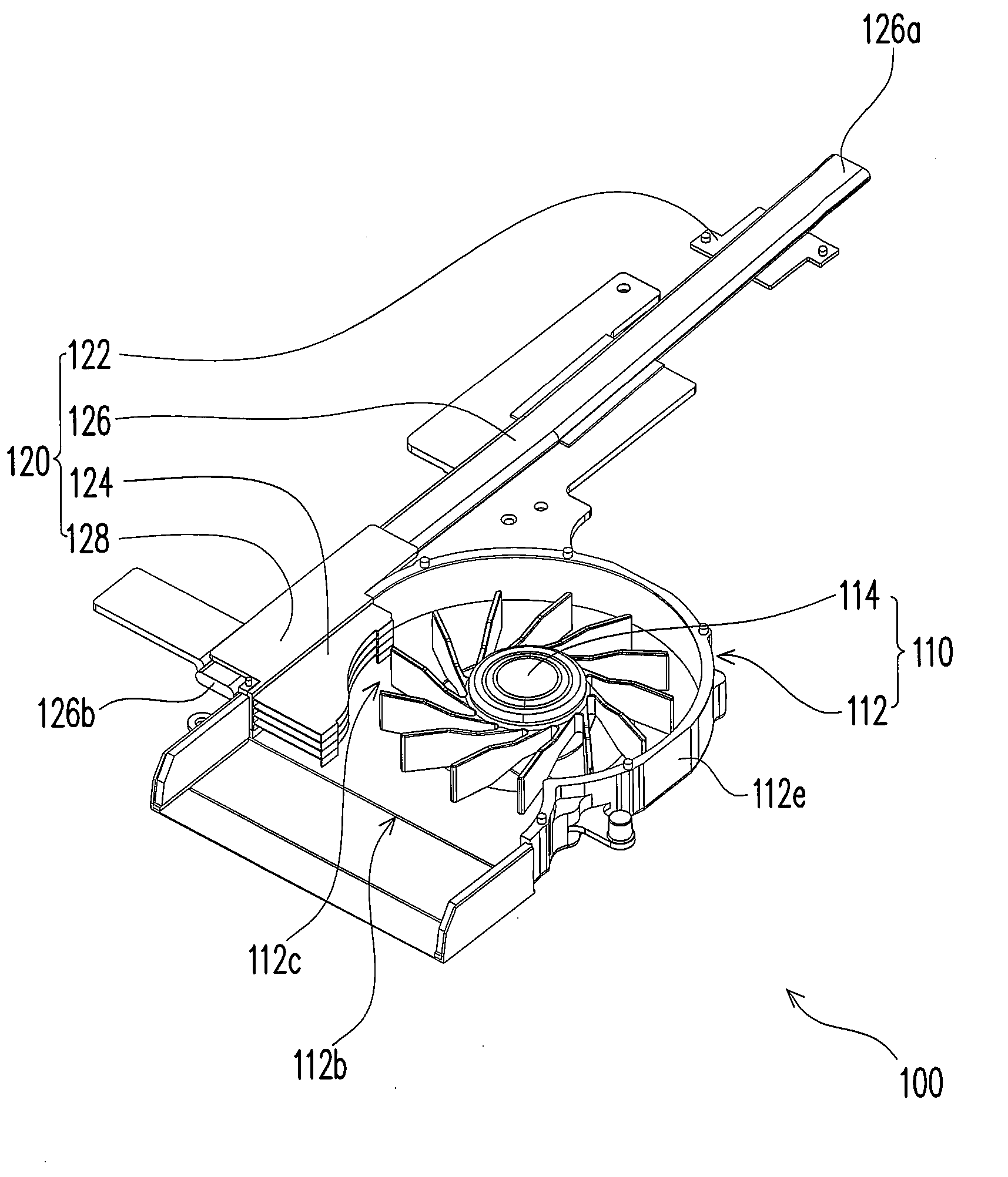
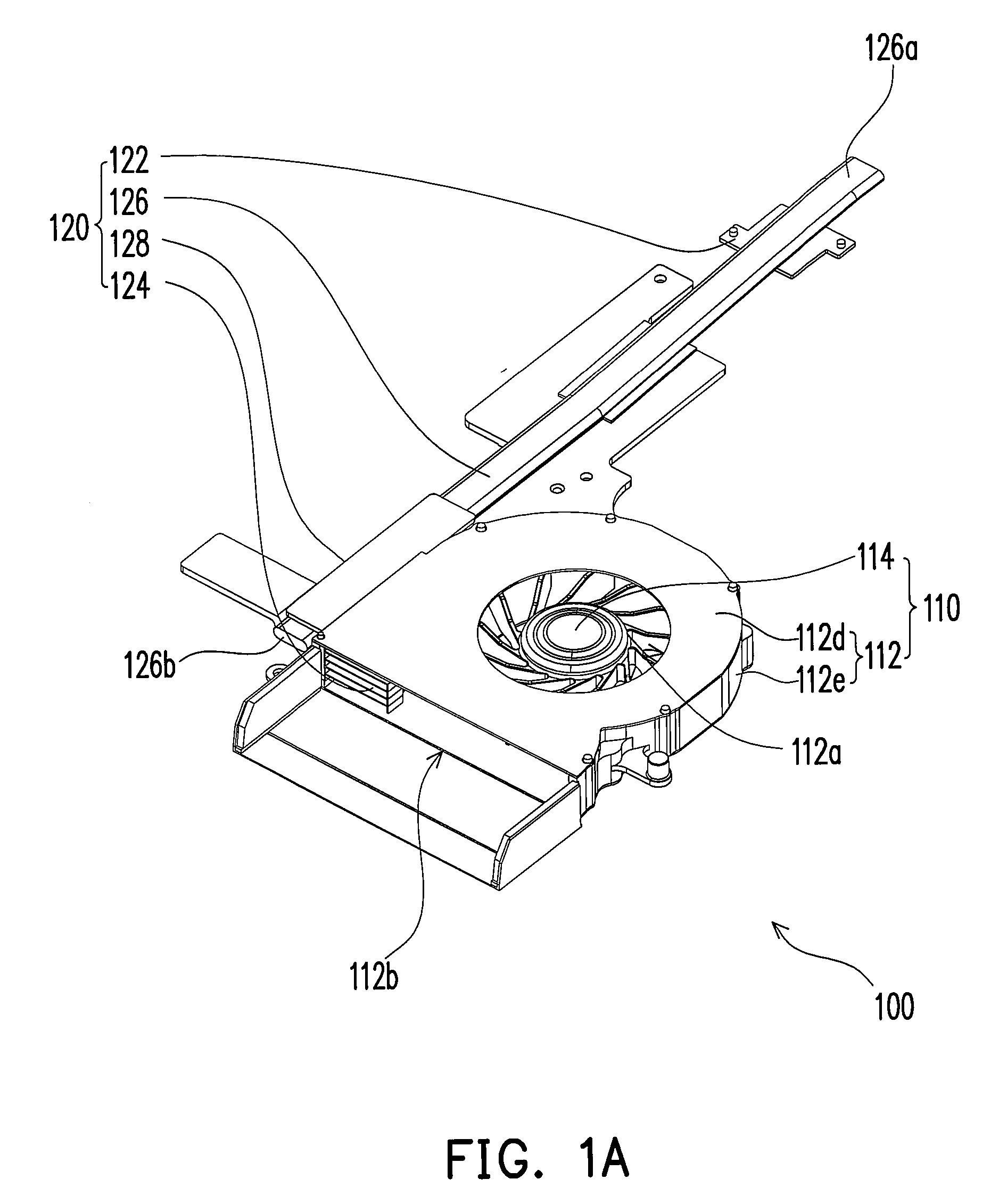
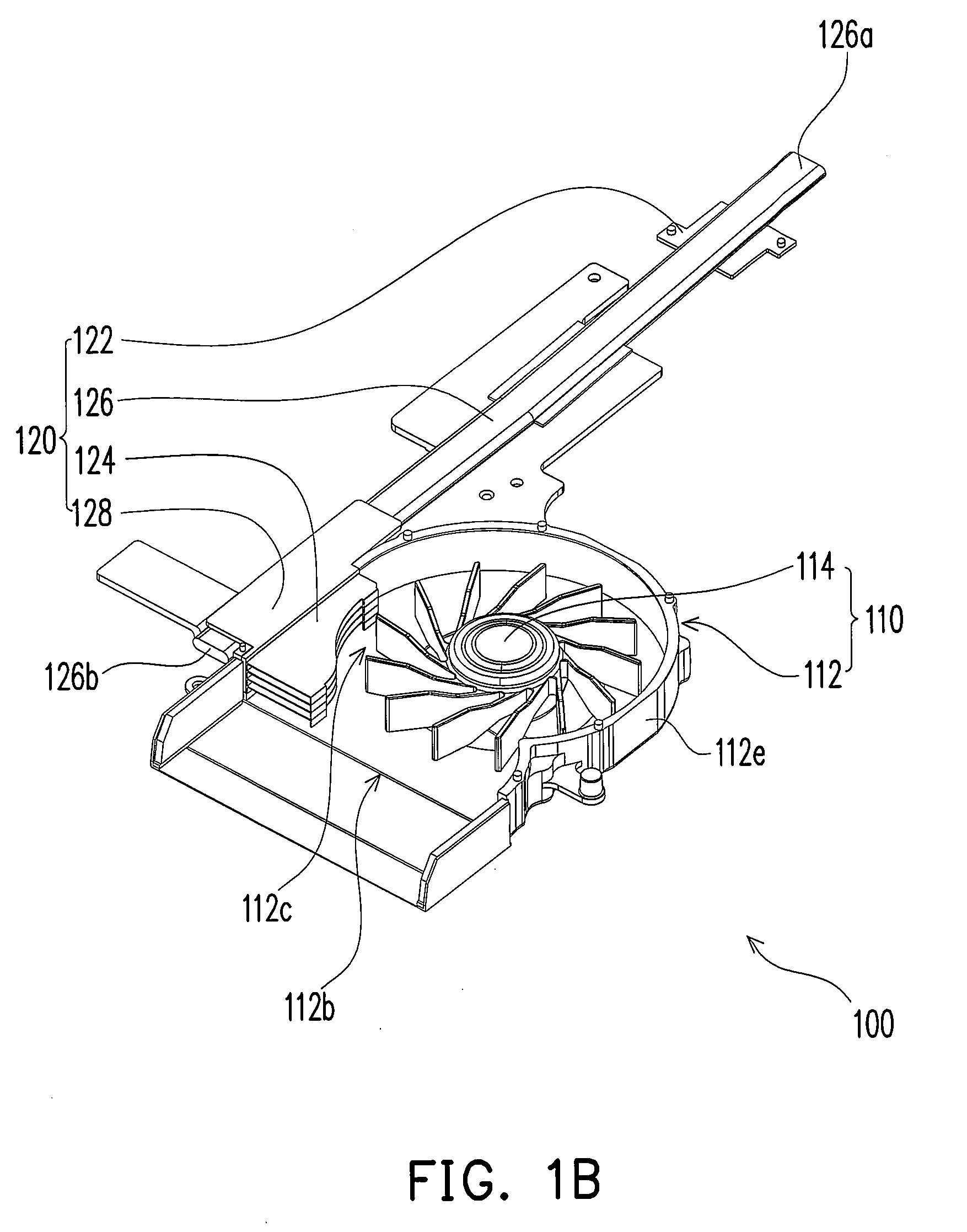
[0017]FIG. 1A is a three-dimensional schematic diagram showing the heat dissipation module of an embodiment of the invention, FIG. 1B is a schematic diagram showing the heat dissipation module in FIG. 1 after the upper cover of the frame is removed, and FIG. 1C is a partial exposed diagram showing the heat dissipation module in FIG. 1A. As shown in FIG. 1A, FIG. 1B and FIG. 1C, a heat dissipation module 100 in the embodiment is suitable to dissipate the heat for an electronic device, such as a notebook computer. Specifically, the inner of the notebook computer always has a central processing unit (CPU), a north bridge chip, a south bridge chip or other chips generating high heat power in the working state. Therefore, the heat dissipation module 100 of the embodiment is suitable to be provided on the above chips to effectively dissipate the heat for the chips, and further to enable the notebook computer to normally work. The heat dissipation module 100 of the embodiment is illustrate...


PUM


Abstract

A heat dissipation module including a fan and a first heat dissipation unit is provided. The fan has a frame and a blade set provided in the frame. The frame has an air inlet and an air outlet, and a flow channel communicating the air inlet and the air outlet is formed between the blade set and the frame. The first heat dissipation unit includes a first heat dissipation base, a first radiating fin assembly located inside the frame wall of the fan on the flow channel, and a first heat pipe which is connected between the first heat dissipation base and the first radiating fin assembly.

Description

CROSS-REFERENCE TO RELATED APPLICATION[0001]This application claims the priority benefit of Taiwan application serial no. 96125627, filed on Jul. 13, 2008. The entirety of the above-mentioned patent application is hereby incorporated by reference herein and made a part of specification.BACKGROUND OF THE INVENTION[0002]1. Field of the Invention[0003]The invention relates to a heat dissipation module and, more particularly, to a heat dissipation module of a notebook computer.[0004]2. Description of the Related Art[0005]In recent years, along with the enormous progress of the computer technology, the operating speed of the computer is continuously increased, and heat generating power of electronic components in a computer housing also continuously rises. To prevent the electronic components from being overheated and temporarily or permanently losing effectiveness in the computer housing, therefore, how to dissipate the heat for the electronic components which generate the heat is an im...

Claims


Application Information

Patent Timeline
IPC IPC(8): H01L23/467
CPCH01L23/427H01L23/467H01L2924/0002H01L2924/00
Inventor HSIAO, MING-YANG
Owner ASUSTEK COMPUTER INC
Learn More