

Device for the separative machining of components made from brittle material
- Summary
- Abstract
- Description
- Claims
- Application Information
AI Technical Summary
Benefits of technology
Problems solved by technology
Method used
Image


Examples
first embodiment
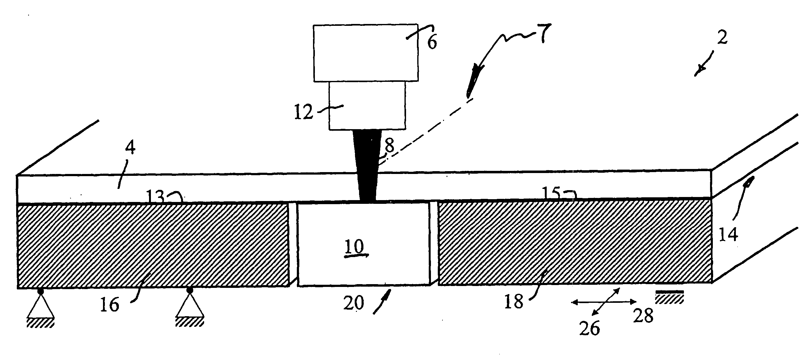
[0045]FIG. 1 shows a device 2 according to the invention for the separative machining of components made from brittle material, such as for example glass, ceramics, glass ceramics, or the like, by generating a thermally induced stress crack on the component in a separation zone. In this embodiment the device 2 serves to sever a component 4 formed by a glass pane. The device 2 comprises a laser 6 for directing a laser beam 8 onto the component to be machined, such that the component partially transmits the laser beam 8 with partial absorption at least twice simultaneously or serially along a separation zone 7, in which the thermally induced stress crack 9 forms, substantially at the same point or at points with little distance relative to each other. For this purpose, the device 2 comprises a first reflector 10 arranged at the side facing away from the laser 6, and a second reflector 12 arranged on the side of the laser 6. During the operation of the device 2 the laser beam 8 is refl...
second embodiment
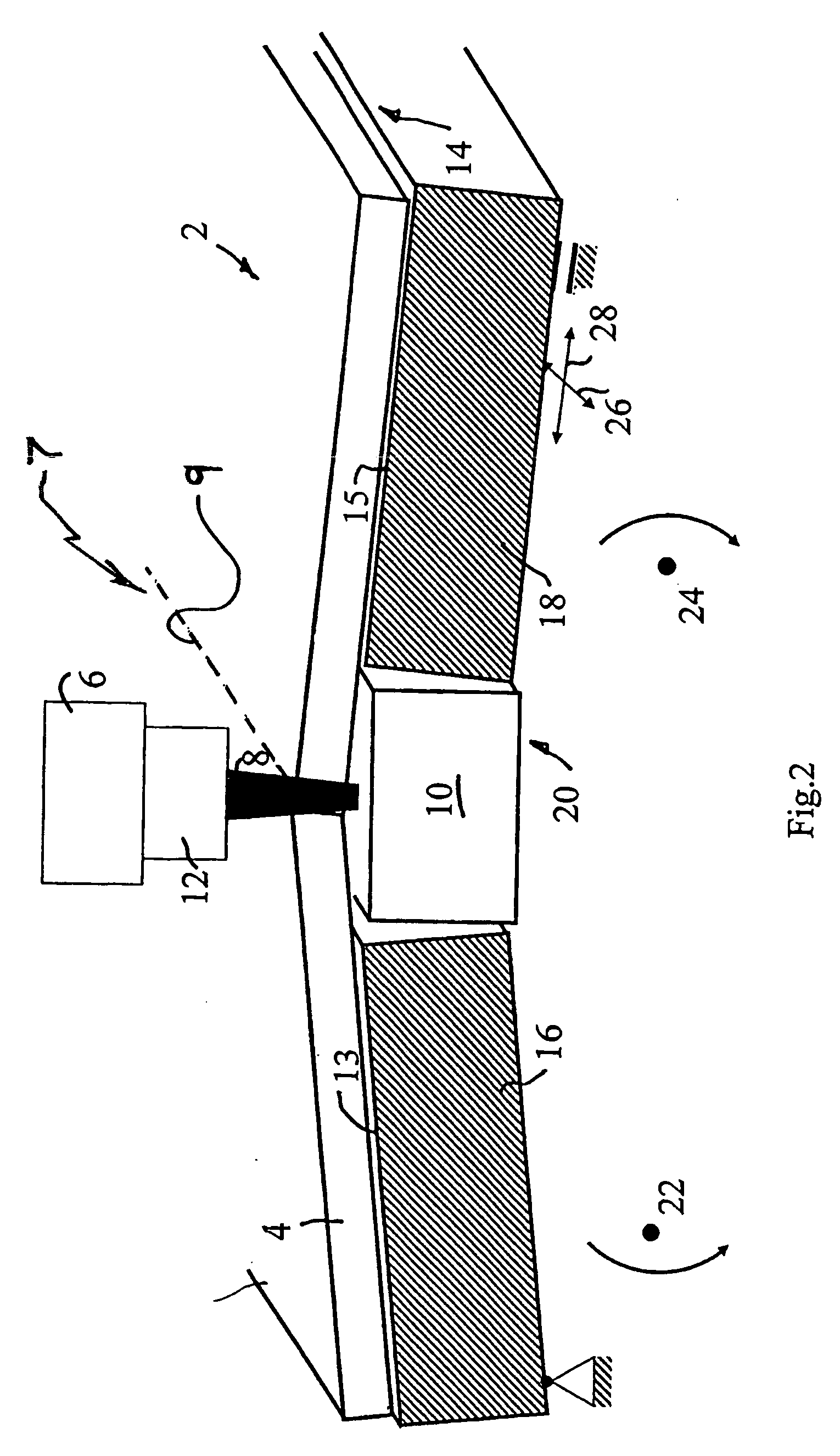
[0049]FIG. 3 illustrates a device 2 according to the invention that differs from the embodiment pursuant to FIG. 1 in that only the bearing element 18 can be swiveled around a swiveling axis 24, while the bearing element 16 is configured in a stationary position.
third embodiment
[0050]FIG. 4 shows a device 2 according to the invention that differs from the embodiment illustrated in FIG. 1 in that the device to supply the component 4 with mechanical stresses are not formed by the bearing elements 16, 18, but rather that a separate supply element 30 is provided, at whose side facing the component 4 the first reflector 10 is formed. To supply the component 4 with mechanical stresses the supply element 30 can be brought in contact with such component 4, with said supply element 30 being adjustable in vertical direction in the illustrated embodiment for this purpose, as indicated by an arrow 32 in FIG. 4. To supply the component 4 with mechanical stresses the supply element 30 is brought in contact with the component 4 and exerts a compressive force on the component 4, so that bending stresses form in said component 4.
PUM
| Property | Measurement | Unit |
|---|---|---|
| Pressure | aaaaa | aaaaa |
| Mechanical properties | aaaaa | aaaaa |
| Brittleness | aaaaa | aaaaa |
Abstract
Description
Claims
Application Information