Electrical rotary machine and method of manufacturing the same

a technology of electric rotary machines and rotary cores, which is applied in the direction of windings, dynamo-electric components, and magnetic circuit shapes/forms/construction, etc., can solve the problems of reducing heat resistance between the element wires and the cores, and achieves the reduction of the temperature of the element wires, reducing heat resistance, and reducing heat resistance. value

Inactive Publication Date: 2009-01-15
HITACHI LTD
View PDF3 Cites 23 Cited by
  • Summary
  • Abstract
  • Description
  • Claims
  • Application Information

AI Technical Summary

Benefits of technology

[0011]Spaces, both between the coils and the core, and between the adjacent element wires, are filled with the heat-conductive insulating resin, which reduces heat resistance between the element wires and the core. Consequently, the temperature of the element wires is decreased. The electrical rotary machine of the present invention can obtain a necessary insulating property by filling the spaces between the coils and the core with the heat-conductive insulating resin.
[0012]The electrical rotary machine of the present invention can reduce the heat resistance value.

Problems solved by technology

Spaces, both between the coils and the core, and between the adjacent element wires, are filled with the heat-conductive insulating resin, which reduces heat resistance between the element wires and the core.

Method used


Image

  • Electrical rotary machine and method of manufacturing the same
  • Electrical rotary machine and method of manufacturing the same
  • Electrical rotary machine and method of manufacturing the same

Examples


first embodiment

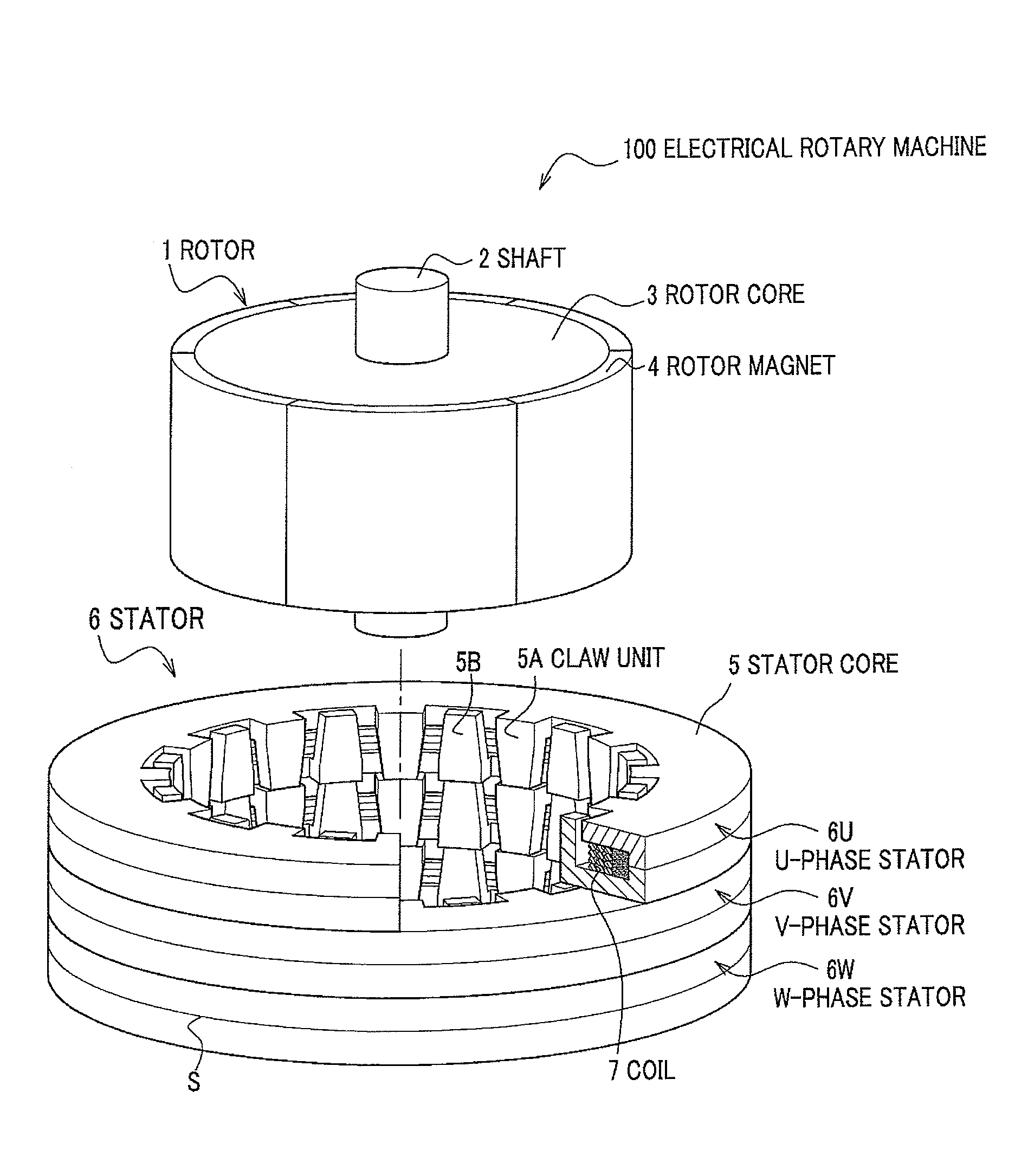
[0023]FIG. 1 shows a three-phase claw-pole electrical rotary machine of a first embodiment of the present invention. The three-phase claw-pole electrical rotary machine includes a stator core of three-dimensional claw-pole structure which allows a reduction in size, achieves a high motor torque, and improves an efficiency of outputting.

[0024]In FIG. 1, an electrical rotary machine 100 includes a rotor 1 and a stator 6 of which three phases (6U, 6V, and 6W) are connected in an axial direction. The rotor 1 includes a shaft 2, a rotor core 3, in which the shaft 2 is inserted, and the even number of rotor magnets 4 disposed on an outer circumferential face of the rotor core 3. The stator 6 includes stator cores 5 (core of the electrical rotary machine) and coils 7. Elements marked with the same number in FIG. 1 are common in other figures.

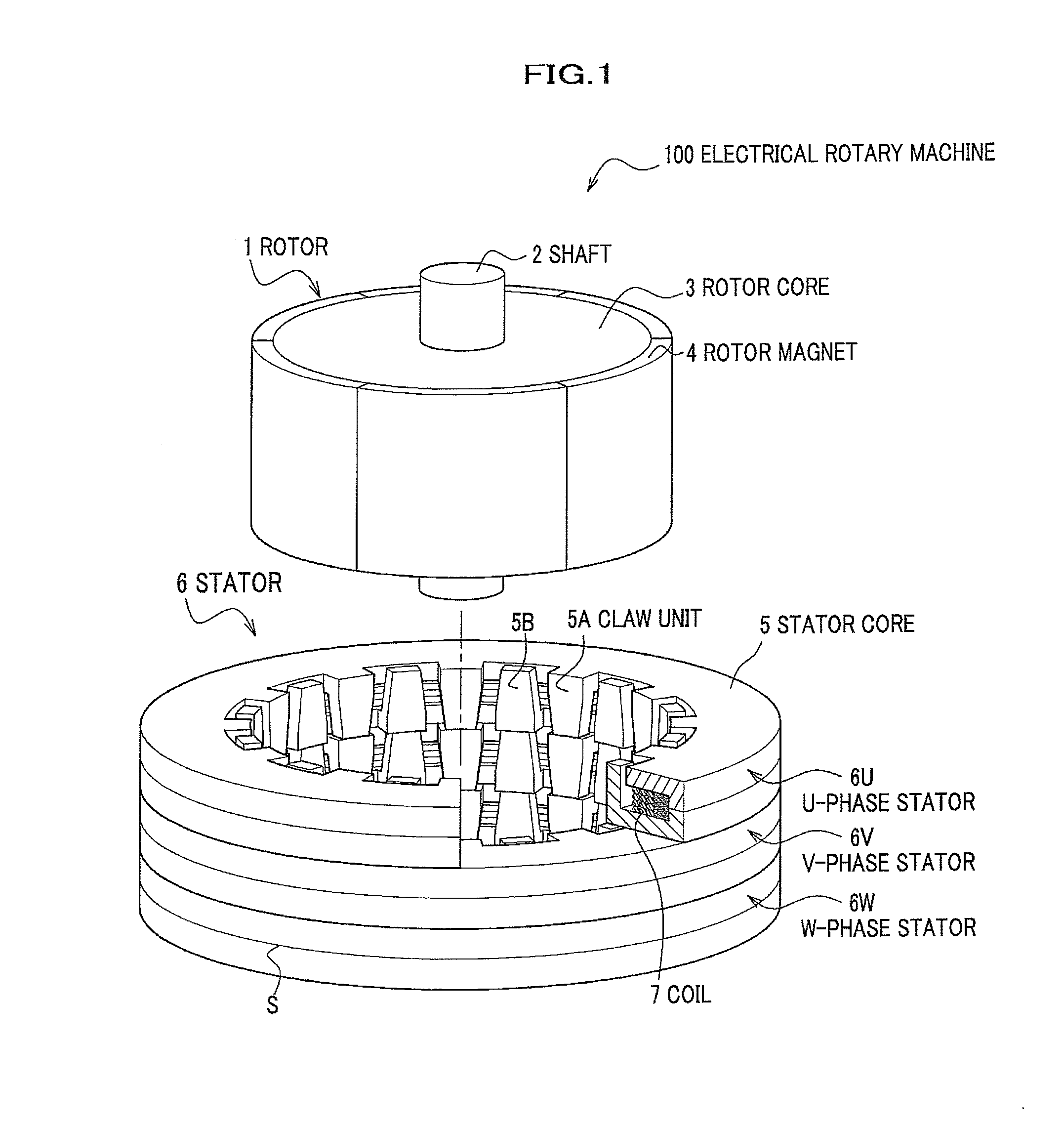
[0025]FIG. 2 shows a perspective view of a structure of the stator 6. The stator 6 for one of three phases includes two stator cores 5C and 5D which e...

second embodiment

[0041]The claw-pole electrical rotary machine using the coil 7 is described in the first embodiment. An open-slot synchronous machine using a distributed winding coil will be described in a second embodiment.

[0042]The synchronous machine (electrical rotary machine) is driven by an inverter which converts a direct electric power supplied by a battery into an alternate electric power, which is favorable so as to achieve a high output and control a weak magnetic field. It is important for the synchronous machine to obtain a high heat conductivity in order to achieve a high output.

[0043]FIG. 9 shows a cross-sectional view on a plane along the axial direction of rotation of an electrical rotary machine 110 of the second embodiment. As shown in FIG. 9, the electrical rotary machine 110 of the second embodiment includes a stator 21, and a rotor 1 disposed via a vacant space on an inner circumferential side of the stator 21 and held rotatable. The stator 21 and the rotor 1 are held in a hou...

modified embodiment

[0052]The present invention is not limited to the embodiments, but may be modified as described below.

[0053]In the embodiments, the spaces between the stator core 5 and the coils 7 of the stator are impregnated with the resin. A rotator (rotor), in which the coils 7 are wound, can be impregnated with the resin. The rotator core described in claims of the present invention includes the stator core and the rotor core.

[0054]In the second embodiment, the synchronous machine is used, but an induction machine can be applied as well.


PUM

PropertyMeasurementUnit
diameteraaaaaaaaaa
power densityaaaaaaaaaa
heat-conductiveaaaaaaaaaa

Abstract

An electrical rotary machine includes coils including element wires wound, and a core holding the coil, wherein spaces, both between the coils and the core, and between the adjacent element wires, are filled with a heat-conductive insulating resin. A method of manufacturing the electrical rotary machine includes a first step of impregnating the coils and filling the space between the adjacent element wires with the heat-conductive insulating resin, and a second step of impregnating the coils and the core and filling the space between the coils and the core with the heat-conductive insulating resin.

Description

CROSS-REFERENCE TO RELATED APPLICATION(S)[0001]This application claims the foreign priority benefit under Title 35, United States Code, § 119 (V1)-(d), of Japanese Patent Application No. 2007-182001A, filed on Jul. 11, 2007 in the Japan Patent Office, the disclosure of which is herein incorporated by reference in its entirety.BACKGROUND OF THE INVENTION[0002]1. Field of the Invention[0003]The present invention relates to an electrical rotary machine in which an element wire is wound on a core, and a method of manufacturing the electrical rotary machine.[0004]2. Description of the Related Art[0005]Electrical rotary machines such as an electric motor and an electric generator are demanded to achieve a high output, enable a reduction in size, and obtain an insulating property so as to operate on a high voltage. Electrical rotary machines as described below are conventionally used. For example, JP58-064015A discloses an insulating method of repeating steps a plurality of number of times...

Claims


Application Information

Patent Timeline
Patent Type & Authority Applications(United States)
IPC IPC(8): H02K1/16H02K15/12
CPCH02K3/18H02K3/34Y10T29/49009H02K5/08H02K15/12H02K3/345
Inventor YOSHITAKE, YUICHIRO
Owner HITACHI LTD
Why Eureka
Try Eureka